Electronics / Networking
Digitus 16-Port Gigabit Switch DN-80118 User Guide
Quick installation guide for the Digitus 16-Port Gigabit Switch (DN-80118). Includes setup instructions, hardware specifications, and network connection diagrams.
Table of contents
Manual images
Click an image to enlargeQuick guide from the manual
This guide provides essential instructions for installing and operating the Digitus 16-Port Gigabit Switch (DN-80118). Before installation, ensure you have all components and a suitable 10-inch server cabinet or housing. The switch is unmanaged and features a fanless design for quiet operation.
Product overview
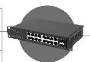
The switch provides 16 Gigabit RJ45 ports and 2 SFP uplink ports with 1 Gigabit bandwidth. It supports a backplane bandwidth of 36 Gbps, making it ideal for small home or company networks. The power adapter is integrated into the housing.

Hardware installation
Package contents:
- 1x Switch
- 1x AC power cord
- 1x Quick Installation Guide
Installation steps:
- Unpack the switch and verify all contents are present and undamaged.
- Ensure the installation location provides proper heat dissipation and adequate ventilation.
- Do not place heavy objects on top of the switch.
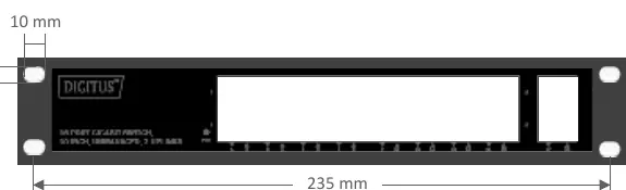
- If mounting in a 10-inch cabinet, use the provided hole spacing (235 mm width).
Power connection
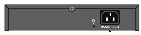
The switch supports input voltages of 100–240 V AC. Connect the AC power cord to the rear panel connector and then to a grounded power outlet. Ensure the power cable is fully secured. Warning: Do not turn on the power switch before all cables are connected to avoid power surges that may damage the device.
Network connection
Use Cat 5 or higher Ethernet cables for network connections. The switch is compatible with various devices, including IP cameras and network video recorders. Connect your devices to the RJ45 ports on the front panel.
Technical specifications
Performance:
- Forwarding rate: 10/100/1000 Mbps
- Switching fabric: 36G
- MAC addresses: 8K
Environment:
- Operating temperature: 0°C to 40°C
- Storage temperature: -10°C to 70°C
- Relative humidity: 20% to 85% (non-condensing)
Physical:
- Dimensions: 252 x 150 x 42 mm
- Casing: Metal
Practical help
Common problems
Power LED is not lit
Ensure the power cable is securely connected to the switch and the power outlet.
No network connection
Verify that the Ethernet cable is Cat 5 or higher and properly connected to both the switch and the device.
Switch overheating
Ensure there is adequate ventilation around the switch and remove any heavy objects placed on top of it.
Before use
- Verify package contents (Switch, AC power cord, QIG)
- Inspect power cord for damage
- Ensure 10-inch rack or housing is ready
- Check for adequate ventilation space
Specs in practice
- Backplane bandwidth
- 36 Gbps total switching capacity for data traffic.
- Input voltage
- 100-240V AC, 50/60Hz power requirement.
- Operating temperature
- Safe operating range is 0°C to 40°C.
Images and diagrams
- Front panel shows LED indicators and network ports
- Rear panel shows AC power connector and grounding point
- Network connection diagram illustrates IP camera and NVR setup
Model compatibility
- Requires Cat 5 or higher Ethernet cables
- Designed for 10-inch server cabinets

Manual page author
Michael Turner
Technical manual editor
Reviews PDF manuals for structure, safety notes, and practical product details so readers can find the right information quickly.