Industrial / Valves
Installation Guide for Danfoss Solenoid Coils Types BB, BE, BF, BG, and BN
Comprehensive installation guide for Danfoss solenoid coils (Types BB, BE, BF, BG, and BN). Includes torque specifications, wiring instructions, safety precautions for flammable refrigerants, and technical data.
Quick answers from the manual
Quick answer
- This guide covers the installation, safety, and technical specifications for Danfoss solenoid coils (Types BB, BE, BF, BG, and BN). It details torque requirements, wiring, and safety precautions for flammable refrigerants. p. 1, 2
Key actions
- Install a fuse ahead of the coil (rated current: 2x rated current, medium time lag). p. 1, 2
- Ensure the O-ring is in place on the valve. p. 1, 2
Technical specifications
| Parameter | Value | Meaning | Pages |
|---|---|---|---|
| Ambient Temperature | -40°C to +80°C | Operating temperature range depending on coil type and voltage. | p. 1, 2 |
| Ball pressure test | 200 °C | Thermal resistance of the material. | p. 1, 2 |
Where to find it in the PDF
- Installation and Technical Data p. 1, 2
Table of contents
Manual images
Click an image to enlargeImportant Information
This document provides installation and safety instructions for Danfoss solenoid coils, including types BB, BE, BF, BG, and BN. Installation and maintenance must be performed only by qualified personnel. Always disconnect the power supply before dismounting the coil.
Installation Instructions
Follow these steps to ensure correct installation:
- O-Ring: Ensure the O-ring is correctly placed on the valve to prevent moisture from penetrating the coil.
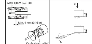
- Cable Gland: If the coil is used as an independently mounted control, the end-user must use a plastic cable gland with strain relief.
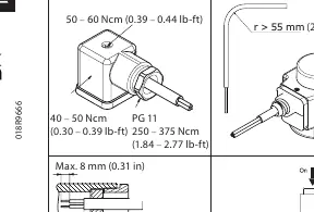
- Torque Values: Adhere to the specified torque values to prevent damage:
- PG 11: 250 – 375 Ncm (1.84 – 2.77 lb-ft)
- PG 13.5: 320 – 370 Ncm (2.36 – 2.73 lb-ft)
- Coil mounting: 50 – 60 Ncm (0.39 – 0.44 lb-ft)
- Philips bits no. 1: 40 – 50 Ncm (0.30 – 0.39 lb-ft)
- Torx TX10: 80 – 90 Ncm (0.59 – 0.66 lb-ft)
- Cable Requirements: Suitable cable diameter is ø6.6 – ø11 mm (ø0.26 – ø0.43 in) with 0.75 – 1.5 mm² (21 – 15 AWG) flexible cord.
Safety Precautions
Flammable Refrigerants: The 13.5 mm coil (IP67) is validated for use with R152A, R32, R290, R600, R600a, R1234yf, and R1234ze. Ensure there is no spark or arc on the spade connection during application.
Fuse Protection: Always install a fuse ahead of the coil to avoid short circuits. The rated current should be two times the rated current of the coil, with a medium time lag.
Environmental Conditions: Avoid direct exposure to alkaline conditions; use in neutral conditions is recommended. The coil must be used in an area with a pollution degree of no more than 2.
Technical Specifications
The coils operate within an ambient temperature range of -40°C to +80°C (depending on the specific model and voltage). Enclosure ratings vary by type (IP00, IP20, IP65, IP67). The impulse withstand voltage is 4.0 kV at altitudes below 4000 m (or 2000 m for specific plug types).
Manufacturer information
Danfoss A/S
Practical help
Common problems
Short circuit risk
Always install a fuse ahead of the coil (rated current: two times of rated current, time lag: medium).
Moisture ingress
Ensure the O-ring is in place on the valve and use a cable gland with strain relief for independently mounted controls.
Sparking at connection
Ensure there is no spark or arc on the spade connection during application, especially when using flammable refrigerants.
Before use
- Verify the coil type (BB, BE, BF, BG, BN) matches your system requirements.
- Ensure installation is performed by qualified personnel only.
- Disconnect power before dismounting the coil.
- Check that the O-ring is present and correctly seated on the valve.
- Use a plastic cable gland with strain relief for independent mounting.
- Verify the ambient temperature is within the specified range (-40°C to +80°C).
Specs in practice
- Pollution Degree (PD)
- PD3/PD4 indicates the environment the coil is suitable for; this product is rated for use in areas with pollution degree 2 or lower.
Images and diagrams
- Torque diagrams show the specific tightening force (in Ncm and lb-ft) for different assembly points.
- Cable strain relief diagram illustrates the correct cable bending radius (r > 55 mm) and cable preparation.
- Connection diagrams show the wiring configuration for different coil types (Spade, Plug, Terminal box).
Model compatibility
- Validated for R152A, R32, R290, R600, R600a, R1234yf, and R1234ze.
- The 13.5 mm coil (IP67) is NOT verified for ATEX or IECEx zone 2 compliance.
- Only validated for systems in compliance with ISO 5149 and IEC 60335.

Manual page author
Michael Turner
Technical manual editor
Reviews PDF manuals for structure, safety notes, and practical product details so readers can find the right information quickly.