HVAC / Compressor Controllers
User Manual for Danfoss BD35/50F Electronic Control Unit
Comprehensive user guide for the Danfoss electronic control unit for BD35/50F compressors. Includes installation instructions, wiring diagrams, battery protection settings, speed control configuration, and LED troubleshooting codes.
Table of contents
Manual images
Click an image to enlargeQuick Guide
This document provides installation and configuration instructions for the Danfoss electronic control unit used with BD35/50F compressors. The unit is designed to operate on both 12V and 24V systems automatically. Key requirements include direct battery connection, proper fuse installation, and adherence to cable cross-section specifications to prevent voltage drops.
Installation
The electronic control unit must be mounted on the compressor by securing the cover under the screw head. Wiring connections are as follows:
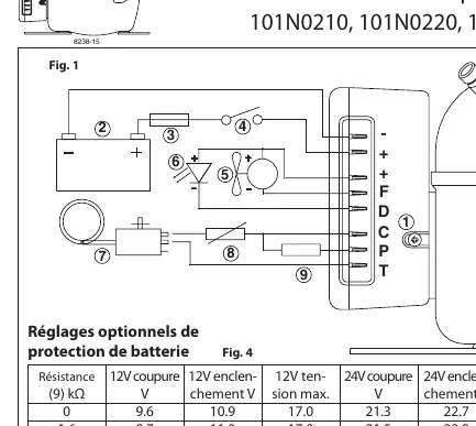
- Battery Connection: Connect directly to the battery terminals. Positive (+) to +, Negative (-) to -. The unit is protected against reverse polarity.
- Fuse: A fuse must be installed on the positive cable as close to the battery as possible. Use a 15A fuse for 12V systems and a 7.5A fuse for 24V systems.
- Thermostat: Connect the thermostat between terminals C and T.
- Fan: Connect a 12V fan between terminals + and F. The output voltage between + and F is regulated to 12V, regardless of the supply voltage.
- Switch: If an on/off switch is installed, it must be rated for at least 20A.
Battery Protection
The compressor stops and restarts based on voltage limits measured at the control unit terminals. Standard settings are pre-configured. You can customize these limits by connecting a resistor between terminals C and P. For solar applications without a battery, a 220 kΩ resistor is recommended.
Speed Control
The compressor speed can be adjusted using a resistor connected to the control circuit:
- Standard Speed: With no resistor, the compressor runs at a constant 2,000 rpm (for 101N0210/101N0220 units).
- Variable Speed: By mounting a resistor between terminals C and T, the speed can be adjusted between 2,000 and 3,500 rpm.
- AEO Mode: For 101N0300 units, the compressor automatically adjusts speed based on cooling demand.
Troubleshooting
If the electronic control unit detects a fault, an optional LED connected between terminals + and D will flash. The number of flashes indicates the specific error:
- 5 Flashes: Thermal cutout (system overload or high ambient temperature).
- 4 Flashes: Motor speed too low (system overload, cannot maintain 1,850 rpm).
- 3 Flashes: Fan overcurrent (fan draws > 1A).
- 2 Flashes: Motor start error (rotor blocked or differential pressure > 5 bar).
- 1 Flash: Battery protection (voltage outside limits).
Technical Specifications
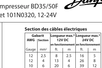
Ensure cable cross-sections meet the requirements based on the distance between the battery and the control unit. Maximum ambient temperature is 55°C. The unit features integrated thermal protection.
Manufacturer information
Danfoss A/S
Practical help
Common problems
Compressor stops due to thermal cutout
Check for system overload or high ambient temperature (above 55°C).
Motor speed too low
The system is overloaded and cannot maintain the minimum 1,850 rpm.
Fan not working or error code 3
The fan is drawing more than 1A; check fan specifications and wiring.
Motor fails to start (2 flashes)
Check if the rotor is blocked or if the differential pressure in the cooling system is too high (> 5 bar).
Battery protection error (1 flash)
The supply voltage is outside the defined cut-out/cut-in limits.
Before use
- Ensure the control unit is connected directly to the battery terminals.
- Install a fuse on the positive cable (15A for 12V, 7.5A for 24V).
- Verify cable cross-section matches the distance to the battery (see Fig 2).
- Ensure the fan is 12V, regardless of system voltage (12V or 24V).
- Check that the thermostat is connected between terminals C and T.
Specs in practice
- 12V/24V Operation
- The module automatically detects and operates on either 12V or 24V DC.
- Max Ambient Temp
- The control unit can operate in ambient temperatures up to 55°C.
Images and diagrams
- Fig 1: Wiring diagram showing connections for battery, thermostat, fan, and resistor.
- Fig 2: Cable section requirements based on length and voltage.
- Fig 3 & 4: Battery protection voltage settings.
- Fig 5: Resistor values for specific motor speeds.
Model compatibility
- Compatible with BD35/50F compressors.
- 101N0300/101N0320 units support AEO mode.
- Always use a 12V fan even on 24V systems.

Manual page author
Michael Turner
Technical manual editor
Reviews PDF manuals for structure, safety notes, and practical product details so readers can find the right information quickly.