HVAC / Compressor Controllers
Danfoss 101N0290 Electronic Unit for BD Compressors
Quick guide for the Danfoss 101N0290 electronic unit. Includes wiring diagrams, battery protection settings, compressor speed configuration, and LED error code troubleshooting.
Table of contents
Manual images
Click an image to enlargeQuick guide from the manual
The Danfoss 101N0290 is a dual-voltage (12V/24V DC) electronic unit designed for BD compressors. It features built-in thermal protection, battery protection, and supports AEO (Adaptive Energy Optimizing) speed mode. Proper installation requires direct connection to the battery with appropriate fusing and wire sizing to prevent voltage drops.
Device Description
This electronic unit manages compressor operation based on voltage limits and cooling demand. It includes connections for a thermostat, an optional fan, and an optional LED for error diagnostics. The unit automatically stops if the temperature becomes too high or if battery voltage falls outside the designated limits.
Installation and Power Supply
Installation: Connect the terminal plug from the electronic unit to the compressor terminal. Mount the unit on the compressor by snapping the cover over the screw head.
Power Supply: The unit must be connected directly to the battery poles (plus to +, minus to -). To protect the installation, a fuse must be mounted in the positive cable as close to the battery as possible:
- 12V circuits: 30A fuse
- 24V circuits: 15A fuse
If a main switch is used, it must be rated for at least 30A. Avoid extra junctions in the power supply system to prevent voltage drops.
Battery Protection Settings
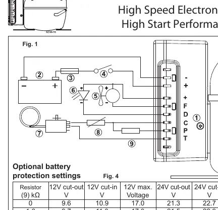
The compressor stops and starts based on voltage limits measured at the terminals. Standard settings are provided in the manual (Fig. 3). Optional settings can be configured by connecting a resistor between terminals C and P (Fig. 4). In AEO speed mode, the compressor adapts its speed to the cooling demand within a voltage range of 9.6V to 31.5V.
Thermostat and Fan Connections
Thermostat: Connect the thermostat between terminals C and T. Direct connection to terminal C allows the unit to adjust speed based on cooling demand. Fixed speeds (2,500 to 4,400 rpm) can be set by installing a resistor between terminals C and T (Fig. 5).
Fan: A fan can be connected between terminals + and F. The output voltage between these terminals is regulated to 12V, so a 12V fan must be used regardless of whether the system is 12V or 24V. The fan output supports a continuous current of 0.5A.
Troubleshooting with LED
An optional 10mA LED can be connected between terminals + and D. If an error occurs, the LED will flash a specific number of times to indicate the fault. The sequence repeats every 4 seconds.
- 5 flashes: Thermal cut-out (system overloaded or high ambient temperature).
- 4 flashes: Minimum motor speed error (system overloaded, cannot maintain 2,450 rpm).
- 3 flashes: Motor start error (rotor blocked or differential pressure >5 bar).
- 2 flashes: Fan over-current cut-out (fan load >1A peak).
- 1 flash: Battery protection cut-out (voltage outside cut-out setting).
Manufacturer information
Danfoss A/S
Practical help
Common problems
Thermal cut-out (5 LED flashes)
The refrigeration system is overloaded or the ambient temperature is too high. Ensure proper ventilation and check system load.
Minimum motor speed error (4 LED flashes)
The system is too heavily loaded and the motor cannot maintain the minimum speed of 2,450 rpm.
Motor start error (3 LED flashes)
The rotor is blocked or the differential pressure in the refrigeration system is too high (>5 bar).
Fan over-current cut-out (2 LED flashes)
The fan is drawing more than 1A peak current. Check fan specifications and wiring.
Battery protection cut-out (1 LED flash)
The battery voltage is outside the configured cut-out setting. Check battery charge and wiring connections.
Before use
- Verify battery voltage is 12V or 24V DC.
- Install a 30A fuse (12V) or 15A fuse (24V) in the positive cable.
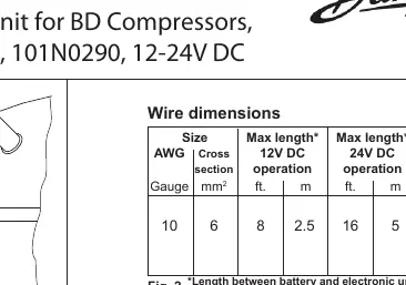
- Ensure wire dimensions match the distance between battery and unit (Fig. 2).
- Connect thermostat between terminals C and T.
- Use a 12V fan for the fan connection (+ and F).
- Ensure the unit is mounted securely on the compressor.
Specs in practice
- Max Ambient Temp
- 55°C; the unit will stop if the electronic unit temperature exceeds this limit.
Images and diagrams
- Fig 1: Wiring diagram showing connections for battery, thermostat, fan, and LED.
- Fig 2: Wire dimension table based on cable length and voltage.
- Fig 3: Standard battery protection voltage settings.
- Fig 4: Optional battery protection settings using a resistor.
- Fig 5: Resistor values for adjusting compressor motor speed.
Model compatibility
- Compatible with BD compressors.
- Fan output is always 12V, regardless of system voltage.
- Requires specific resistor values for fixed speed operation.

Manual page author
Emily Carter
User documentation editor
Prepares concise manual descriptions and highlights the most useful setup, operation, and maintenance information for readers.