Home / Security
Installation Guide for Danfoss 080Z2172 Outdoor Photocell
Quick installation and wiring guide for the Danfoss 080Z2172 outdoor photocell. Includes mounting instructions, wiring diagrams, and technical specifications for light and temperature sensing applications.
Table of contents
Quick guide from the manual
The Danfoss 080Z2172 is an outdoor photocell with an integrated temperature sensor. For optimal performance, the sensor must be mounted four to six feet above the roof line and oriented so that the photo-sensitive element faces north. The sensor is recessed to ensure it remains directional.
Product Overview
This device is designed to sense ambient temperature and light levels. It is commonly used in applications such as lighting control, HVAC systems, and condensing unit control.
Installation and Inspection
The sensor is recessed to be directional. Ensure the following during installation:
- Mount the unit four to six feet above the roof line.
- Orient the unit so the photo-sensitive element faces north.
Wiring Connections
The unit requires specific wiring connections to function correctly:
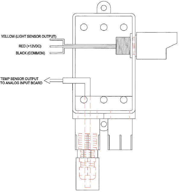
- Yellow wire: Light sensor output (0 - 5 V d.c.)
- Red wire: +12 V d.c.
- Black wire: Common
- Temp sensor output: Pt 1000 Ohm (connects to analog input board)
Technical Specifications
Input Voltage: 10V
Photosensor Range: 0-750 FC (0-8073 Lux)
Operating Temperature (Photocell): 13°F to 140°F (-10°C to 60°C)
Operating Temperature (AKS 12 Sensor): -58°F to 212°F (-50°C to 100°C)
Disposal
This product contains electrical components and must not be disposed of with domestic waste. It must be collected separately as electrical and electronic waste in accordance with local and valid legislation.
Manufacturer information
Danfoss A/S
Practical help
Common problems
Inaccurate light readings
Ensure the sensor is oriented to face north and is mounted 4-6 feet above the roof line to avoid interference.
Before use
- Verify the mounting location is 4-6 feet above the roof line.
- Ensure the sensor is oriented to face north.
- Confirm the power supply is 10V.
- Check that the wiring matches the color-coded diagram (Yellow, Red, Black).
Specs in practice
- Input Voltage
- The unit requires a 10V DC power supply.
- Photosensor Range
- The sensor detects light levels between 0-750 FC or 0-8073 Lux.
- Temp Sensor Output
- Provides a Pt 1000 Ohm signal to the analog input board.
Images and diagrams
- The wiring diagram illustrates the connection points for the light sensor output (Yellow), power (Red), and common (Black).
- The diagram also indicates the connection path for the temperature sensor output to the analog input board.
Model compatibility
- Compatible with lighting control systems.
- Compatible with HVAC systems.
- Compatible with condensing unit control.

Manual page author
David Miller
Documentation analyst
Organizes user manual content into clear summaries, with attention to model details, product context, and everyday usability.