HVAC / Refrigeration Components
User Guide for Danfoss Optyma iCO2 Gas Cooler Replacement
A comprehensive service guide for replacing the gas cooler on the Danfoss Optyma iCO2 condensing unit. Includes step-by-step instructions for preparation, brazing, airtightness testing, vacuuming, and system charging.
Quick answers from the manual
Quick answer
- This guide outlines the procedure for replacing the gas cooler on the Danfoss Optyma iCO2, including preparation, brazing, pressure testing, and vacuuming. p. 3, 5
Key actions
- Prepare unit by releasing nitrogen and opening valves p. 3
- Perform airtightness test at 140bar p. 3, 5
- Vacuum system to 500 µm Hg p. 5
Technical specifications
| Parameter | Value | Meaning | Pages |
|---|---|---|---|
| Airtightness test pressure | 140bar (14MPa) | Pressure for high pressure tubing test | p. 3, 5 |
| Vacuum target | 500 µm Hg (0.67 mbar) | Absolute vacuum level | p. 5 |
Where to find it in the PDF
- Preparation and Removal p. 3
- Piping Diagram p. 4
- Vacuuming and Charging p. 5
Table of contents
Manual images
Click an image to enlargeQuick guide from the manual
This document provides the procedure for replacing the gas cooler on the Danfoss Optyma iCO2 condensing unit. Key safety requirements include wearing appropriate PPE and ensuring the power supply is disconnected before starting. The process involves de-brazing connections, replacing the heat exchanger, performing a high-pressure airtightness test at 140bar, vacuuming the system, and recharging with nitrogen/CO2.
Step 1: Preparation
- Ensure the power supply is turned OFF.
- Release nitrogen through service valves to keep the system dry.
- Turn ON dip switch SW5-7 (Up) and power on the unit to fully open electronically operated valves and electronic expansion valves.
- Remove fan motors from the top panel and disconnect cables from the PCB.
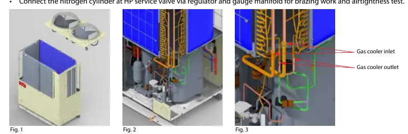
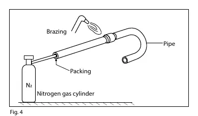
- Remove the top panel, exercising caution as the gas coolers may shift.
- De-braze the inlet and outlet piping connections.
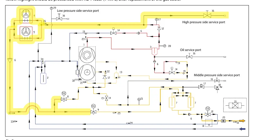
- Connect the nitrogen cylinder at the HP service valve for brazing and testing.
Step 2: Heat exchanger replacement
- Lift the new gas cooler into position.
- Re-braze the piping connections, ensuring you purge with nitrogen to prevent oxidation.
- Use a sufficient amount of brazing rod for connections.
- Clean the inside of low-pressure devices and pipes before use. Always use a pipe cutter; avoid saws or grinders to prevent metal swarf.
Step 3: Airtightness test
- Power off the unit, then set dip switch SW5-7 to OFF and SW5-8 to ON (Up) to fully close valves.
- Apply 140bar (14MPa) of nitrogen from the HP service port.
- Increase pressure in steady increments (10bar, 30bar, 70bar, 100bar, 130bar), pausing for 5 minutes at each step.
- Finally, charge to 140bar and hold for 10 minutes to check for pressure drops or tube deformation.
Step 4: Vacuuming
- Never use the compressor to evacuate the system.
- Connect a vacuum pump to both LP and HP sides.
- Pull the system down to a vacuum of 500 µm Hg (0.67 mbar) absolute.
- Do not use a megohmmeter or apply power to the compressor while under vacuum.
- If no power is available, remove the coil from the medium pressure suction solenoid valve and open it manually with a magnet.
Step 5: Nitrogen and CO2 charge
- For storage, charge a small amount of N2 (0.1bar) to keep the unit dry.
- For on-site operation, charge according to previous commissioning data or use the Danfoss calculation charge tool.
Maintenance
- If components in the medium and low-pressure areas are replaced, follow the same airtightness test procedure as the installation phase.
- Usage pressure for these components is 80.0bar.
Manufacturer information
Danfoss A/S
Practical help
Common problems
System contamination during pipe cutting
Always use a pipe cutter. Avoid saws or grinders, as they produce metal swarf.
Oxidation during brazing
Purge the piping with nitrogen during the brazing process to prevent oxide scale.
Pressure drop during airtightness test
Ensure all connections are brazed correctly and verify the test pressure reaches 140bar.
Before use
- Ensure power supply is OFF before manipulating switches
- Wear appropriate PPE
- Have a nitrogen cylinder with regulator and gauge manifold
- Use a pipe cutter for refrigerant pipes
- Have a vacuum pump ready for evacuation
Specs in practice
- Airtightness test pressure
- 140bar (14MPa) applied to the HP service port.
- Vacuum target
- 500 µm Hg (0.67 mbar) absolute.
- Usage pressure
- 80.0bar for components in medium and low-pressure areas.
Images and diagrams
- Fig 1-3: Shows gas cooler inlet/outlet and removal process.
- Fig 4: Illustrates the brazing setup with nitrogen flow.
- Fig 5: Piping diagram of the Optyma iCO2 system.
- Fig 7: Highlights pressurization points for the airtightness test.
Model compatibility
- Use Danfoss calculation charge tool for refrigerant and oil charge.
- Ensure airtight test report and pressure test report are captured for regulations.

Manual page author
Michael Turner
Technical manual editor
Reviews PDF manuals for structure, safety notes, and practical product details so readers can find the right information quickly.