HVAC / Control Boards
Danfoss AK-XM 205A Extension Module Instructions
Quick guide for the Danfoss AK-XM 205A extension module. Includes installation, wiring diagrams, terminal assignments, and technical specifications.
Quick answers from the manual
Quick answer
- The Danfoss AK-XM 205A is an extension module for refrigeration and AC control, featuring 8 analog inputs and 8 digital outputs. It mounts on a DIN rail and requires careful separation of high and low voltage circuits. p. 1, 2
Key actions
- Mounting the module p. 1
- Connecting wiring p. 2
Technical specifications
| Parameter | Value | Meaning | Pages |
|---|---|---|---|
| Analog Inputs | 8 | Number of AI channels | p. 1, 2 |
| Digital Outputs | 8 | Number of DO channels | p. 1, 2 |
| Max Voltage (DO) | 230V | Maximum switching voltage for digital outputs | p. 1 |
Where to find it in the PDF
- General specs and mounting p. 1
- Wiring and terminal connections p. 2
Table of contents
Manual images
Click an image to enlargeImportant Information
The Danfoss AK-XM 205A is an extension module designed for refrigeration and air conditioning control systems. This document provides essential installation, wiring, and technical data. Always ensure power is disconnected before adding or removing modules to prevent electrical hazards.
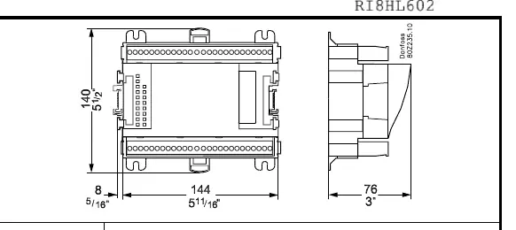
Installation and Mounting
The module is designed for DIN rail mounting. Ensure the environment meets the operating temperature range of -20°C to 55°C (-0°F to 130°F) and humidity levels of 0-95% RH (non-condensing). The device has an IP10 / VBG4 protection rating.
Wiring and Terminal Connections
The module features 8 Analog Inputs (AI) and 8 Digital Outputs (DO). Proper wiring is critical for system operation. Observe the following safety rule: Low and high voltage must not be connected to the same output group.
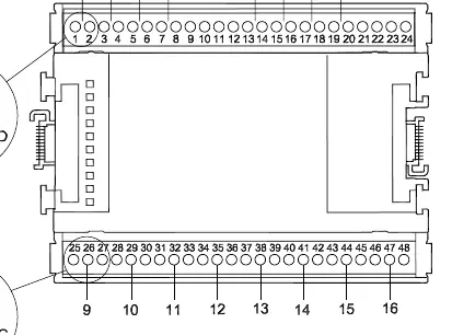
Terminal assignments are as follows:
- AI 1: Terminals 1-2
- AI 2: Terminals 3-4
- AI 3: Terminals 5-6
- AI 4: Terminals 7-8
- AI 5: Terminals 13-14
- AI 6: Terminals 15-16
- AI 7: Terminals 17-18
- AI 8: Terminals 19-20
- DO 1: Terminals 25-26-27
- DO 2: Terminals 28-29-30
- DO 3: Terminals 31-32-33
- DO 4: Terminals 34-35-36
- DO 5: Terminals 37-38-39
- DO 6: Terminals 40-41-42
- DO 7: Terminals 43-44-45
- DO 8: Terminals 46-47-48
Additional power terminals: Terminal 9 (12V), Terminal 10 (5V), Terminal 21 (12V), Terminal 22 (5V).
Technical Specifications
- Analog Inputs (AI): 8
- Digital Outputs (DO): 8
- Max Voltage (DO): 230V
- AC-1 (Ohmic): Max 4A
- AC-15 (Inductive): Max 3A
- Analog Input Max Voltage: 10V
Manufacturer information
Danfoss A/S
Practical help
Common problems
Mixing voltage levels
Ensure low and high voltage are not connected to the same output group.
Module not powering on
Verify connections to terminals 9/10 or 21/22 for 12V/5V supply.
Before use
- Disconnect power before installation or removal.
- Verify DIN rail mounting space.
- Check that operating environment is between -20°C and 55°C.
- Confirm wiring matches the terminal assignment table.
- Ensure high and low voltage circuits are separated.
Images and diagrams
- The wiring diagram shows how to connect sensors (S, P, U) and digital outputs (DO) to specific terminals.
- The address setting diagram illustrates how to configure the module address.
Model compatibility
- Compatible with Pt 1000 sensors.
- Compatible with AKS 32R, AKS 2050, MBS 8250, and AKS 32 pressure transmitters.

Manual page author
Michael Turner
Technical manual editor
Reviews PDF manuals for structure, safety notes, and practical product details so readers can find the right information quickly.