Industrial / I/O Modules
Danfoss AK-XM 205B Extension Module Instructions
Quick guide for the Danfoss AK-XM 205B extension module. Includes wiring diagrams, terminal mapping, signal types, and safety instructions for installation.
Table of contents
Quick guide from the manual
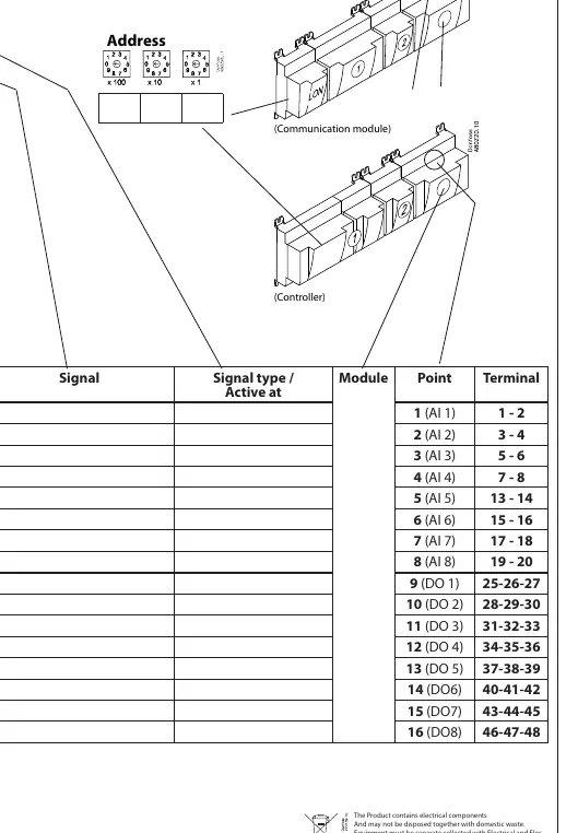
The Danfoss AK-XM 205B is an extension module designed for refrigeration and air conditioning control systems. It features 8 Analog Inputs (AI) and 8 Digital Outputs (DO). Important: Always disconnect power before adding or removing modules. Ensure that low and high voltage circuits are not connected to the same output group to maintain safety distances.
Installation and Wiring
The module utilizes terminals 1 through 48 for various connections. Wiring must be performed according to the specific signal types required for your application.
- Override Switch: The module includes an override switch allowing manual control (OFF / AUTO / ON).
- Address Setting: Use the address switches (x100, x10, x1) to configure the module address.
- Terminal Voltages: Specific terminals provide power for sensors: Terminal 9 (12V), Terminal 10 (5V), Terminal 21 (12V), and Terminal 22 (5V).
Signal Types
The module supports several signal types for inputs and outputs:
- S (Sensor): Pt 1000 ohm/0°C.
- P (Pressure): Compatible with AKS 32R, AKS 2050, MBS 8250, and AKS 32 sensors.
- U (Voltage): Supports 0-5V and 0-10V signals.
- On/Off: Supports external main switch, Day/Night, and Door inputs.
- DO (Digital Output): Supports Comp 1, Comp 2, Fan 1, and Alarm functions.
Technical Specifications
- Operating Temperature: -20°C to 55°C (-0°F to 130°F).
- Humidity: 0 - 95% RH, non-condensing.
- Protection: IP10 / VBG4.
- Relay Ratings: Max 230V; AC-1: max 4A (ohmic); AC-15: max 3A (inductive).
- Safety: UL E357029.
Manufacturer information
Danfoss A/S
Practical help
Common problems
Low and high voltage connected to the same output group
Separate low and high voltage circuits to maintain safety distance and prevent damage.
Module not communicating
Verify the address settings (x100, x10, x1) and ensure terminal connections are secure.
Before use
- Ensure power is disconnected before adding or removing modules.
- Verify voltage requirements for terminals 9, 10, 21, and 22.
- Check signal type compatibility (Pt 1000, Pressure, Voltage).
- Set the correct address using the address switches.
- Confirm load type (ohmic vs inductive) for relay outputs.
Specs in practice
- AC-15 (inductive)
- Maximum 3 A load for inductive loads.
Images and diagrams
- Terminals 1-48 are mapped to specific AI and DO functions.
- Override switch allows manual control (OFF/AUTO/ON).
Model compatibility
- Compatible with Pt 1000 sensors.
- Compatible with AKS 32R, AKS 2050, MBS 8250, and AKS 32 pressure transmitters.

Manual page author
David Miller
Documentation analyst
Organizes user manual content into clear summaries, with attention to model details, product context, and everyday usability.