Industrial / Motor Control
Installation Guide for Danfoss AK-XM 208C Stepper Output Module
Installation guide for the Danfoss AK-XM 208C Stepper Output Module. Includes wiring diagrams, terminal connections, power requirements, and operating specifications.
Quick answers from the manual
Quick answer
- The AK-XM 208C is a stepper output module requiring a 24V AC/DC power supply. It supports 4 stepper valve outputs and 8 analog inputs. Installation requires specific wiring (16 AWG copper) and adherence to safety protocols, including not earthing the '+' and '-' terminals. p. 1, 2
Key actions
- Disconnect power before adding or removing modules. p. 1
- Connect pressure transmitter cable screens only at the end of the module. p. 2
Problems and fixes
Red flash on module
Check for valve error or connection error.
p. 2Technical specifications
| Parameter | Value | Meaning | Pages |
|---|---|---|---|
| Power Supply | 24 V AC/DC | Required input voltage for the module. | p. 1 |
| Valve Output | 24 V d.c. | Output voltage for stepper valves. | p. 1 |
| Max Cable Length | 30 m | Maximum allowed length for valve wiring. | p. 1 |
Where to find it in the PDF
- Installation and Specifications p. 1
- Wiring and Terminal Mapping p. 2
Table of contents
Manual images
Click an image to enlargeQuick guide from the manual
The AK-XM 208C is a stepper output module designed for controlling stepper valves. Key installation requirements include:
- Power: Requires a separate 24 V AC/DC power supply.
- Safety: Ensure power is disconnected before adding or removing modules. Terminals '+' and '-' must not be earthed.
- Wiring: Use 16 AWG or larger wires rated for at least 90 °C (194 °F). Use copper conductors only.
- Centralized Control: The module opens and closes opposite to the AK-XM 208B. It requires a dedicated line up (Comm module + 208C only) with no other modules added.
Installation and Safety
The module is designed for Class II construction. It must be installed in accordance with NEC standards (Class 2 or LPS). The operating environment must be between -20 °C and 55 °C (-0 °F to 130 °F) with 0–95% RH (non-condensing). The connection to the valve must not be broken using a relay.
Wiring and Terminal Connections
The module features specific terminal mappings for various inputs and outputs:
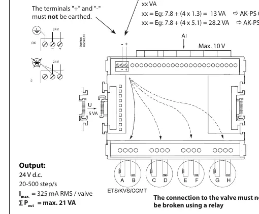
- Valve Outputs: Terminals 25-28 (Step 1), 29-32 (Step 2), 33-36 (Step 3), 37-40 (Step 4).
- Analog Inputs (AI): Terminals 1-2 (AI 1) through 15-16 (AI 8).
- Power/Voltage: Terminal 17 (12 V), Terminal 18 (5 V).
- Status Indicators: Green light indicates valve opens/closes. Red flash indicates a valve error or connection error.
Valve Compatibility
The module supports various valve types, including:
- ETS 12.5 - ETS 400
- KVS 15 - KVS 42
- CCMT 2 - CCMT 8
- CCM 10 - CCM 40
- CTR 20
- CCMT 16 - CCMT 42
Technical Specifications
The module provides 4 stepper valve outputs and 8 analog inputs. The maximum output power is 21 VA. The valve output is 24 V d.c. with a frequency of 20-500 step/s and a maximum current of 325 mA RMS per valve. The maximum cable length is 30 m (Filter AKA 211 must not be used).
Manufacturer information
Danfoss A/S
Practical help
Common problems
Red flash on module
Indicates a valve error or connection error. Check wiring and valve status.
Terminals earthed
The terminals '+' and '-' must not be earthed. Ensure proper isolation.
Valve not operating correctly in centralized control
Ensure AK-XM 208C has a dedicated line up (Comm module + 208C only) and no other modules are added to it.
Before use
- Disconnect power before adding or removing modules.
- Use 16 AWG or larger wires rated for at least 90 °C (194 °F).
- Use copper conductors only.
- Ensure the power supply is 24 V AC/DC.
- Verify that the screen on pressure transmitter cables is connected only at the end of the module.
Specs in practice
- Operating Temperature
- -20 °C to 55 °C (-0 °F to 130 °F).
- Valve Output
- 24 V d.c., 20-500 step/s, max 325 mA RMS per valve.
- Max Cable Length
- 30 meters. Do not use Filter AKA 211.
Images and diagrams
- The wiring diagram shows the connection for stepper valve outputs and the power supply requirements.
- The terminal mapping table on page 2 details the specific terminal numbers for each AI input and valve step output.
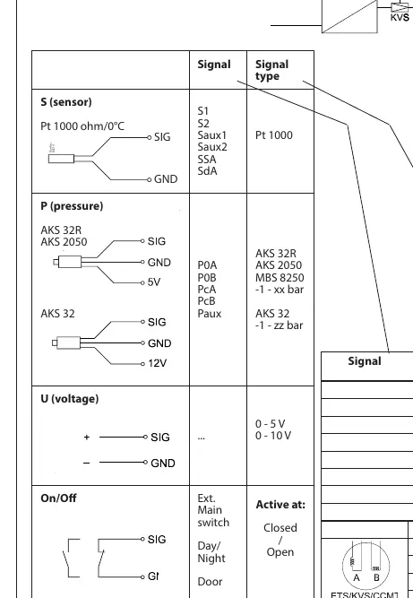
- Sensor wiring diagrams illustrate connections for Pt 1000 sensors, pressure transmitters (AKS 32R, AKS 2050, AKS 32), and voltage inputs.
Model compatibility
- Compatible with ETS, KVS, CCMT, CCM, and CTR valve series.
- Not compatible with Filter AKA 211.
- Requires dedicated line up for centralized control.

Manual page author
David Miller
Documentation analyst
Organizes user manual content into clear summaries, with attention to model details, product context, and everyday usability.