Industrial / Parts & Accessories
Installation Guide for Danfoss Overhaul Kit PMFL 80-6
A comprehensive installation guide and parts breakdown for the Danfoss PMFL 80-6 overhaul kit (Code 027F0635). Includes an exploded view diagram and component specifications for maintenance.
Table of contents
Manual images
Click an image to enlargeQuick guide from the manual
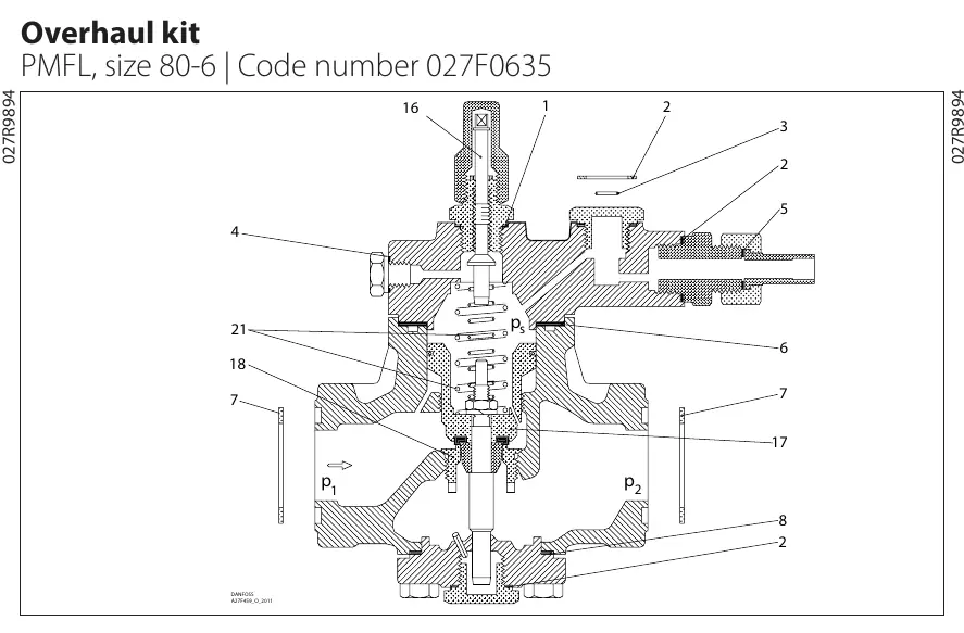
This document serves as the official parts list and assembly reference for the Danfoss PMFL size 80-6 overhaul kit (Code 027F0635). It is intended for technicians performing maintenance or repairs on the PMFL valve. The guide provides an exploded view diagram and a detailed list of components included in the kit.
Exploded view and component identification
The provided diagram illustrates the internal assembly of the PMFL valve. Use the numbered references in the diagram to identify specific components during the disassembly and reassembly process. Ensure that all seals and springs are correctly positioned according to the valve's internal structure.
Parts list and specifications
The overhaul kit contains various gaskets, seals, and springs required for maintenance. The following components are included:
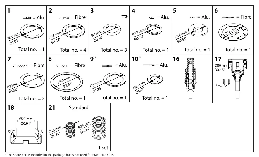
- Gaskets and Seals: Various sizes ranging from 9mm to 80mm, made of Aluminum or Fibre materials.
- Springs: Standard spring sets (items 21).
- Internal components: Various valve parts (items 1-18) required for the overhaul.
Important maintenance notes
Please observe the following conditions when using this kit:
- Compatibility: Some parts included in the package are marked with an asterisk (*) and are not used for the PMFL size 80-6 model. Do not attempt to install these parts.
- Spring Installation: For specific instructions regarding the installation of Weak and Strong spring sets, refer to the separate installation guide DKRCI.PI.GE1.C.
Official resources from the manual
Manufacturer information
Danfoss A/S
Practical help
Common problems
Parts left over after assembly
Some parts included in the kit are marked with an asterisk (*) and are not used for the PMFL size 80-6 model. This is normal.
Before use
- Verify the kit code is 027F0635.
- Consult installation guide DKRCI.PI.GE1.C for spring installation instructions.
- Identify all components using the exploded view diagram before starting disassembly.
- Ensure the valve is depressurized before beginning any maintenance.
Specs in practice
- Code 027F0635
- The specific product code for the PMFL size 80-6 overhaul kit.
Images and diagrams
- The diagram displays the exploded view of the PMFL valve, with numbers 1 through 21 corresponding to the parts list.
- Arrows indicate the flow direction (P1 to P2) and the position of the spring sets (Ps).
Model compatibility
- This kit is specifically for PMFL size 80-6.
- Parts marked with an asterisk (*) are not compatible with size 80-6.

Manual page author
David Miller
Documentation analyst
Organizes user manual content into clear summaries, with attention to model details, product context, and everyday usability.