Electronics / Wireless Receivers
Installation Guide for DMP 1100DI In-Line Wireless Receiver
Comprehensive installation and programming guide for the DMP 1100DI In-Line Wireless Receiver. Includes wiring instructions, panel programming steps, LED status indicators, and technical specifications.
Table of contents
Manual images
Click an image to enlargeQuick Guide
The DMP 1100DI In-Line Wireless Receiver provides two-way, supervised communication for compatible alarm panels. Installation involves programming the panel, wiring the receiver to the keypad bus, and performing an LED survey to ensure proper communication with transmitters.
Description and Compatibility
The 1100DI uses 900 MHz frequency hopping spread spectrum technology to provide up to 32 wireless zones. It is designed for a compact installation anywhere along the panel keypad bus.
- Compatibility: XT30/XT50 Series panels with firmware Version 102 or higher.
- System Limit: Only one 1100 receiver is used per panel.
- Included: 1100DI Receiver with housing, 4-wire harness, and hardware pack.
Programming the Panel
Refer to your panel's programming guide for detailed navigation. After each step, press CMD to advance.
- Access the Programmer menu by entering 6653 (PROG) at a keypad.
- Navigate to SYSTEM OPTIONS and program a HOUSE CODE (1-50).
- When the XT50 displays RECEIVER NO YES, select NO.
- Press CMD until STOP displays, then press a top row select key or area to save.
Wiring and Mounting
Ensure the device is powered down before wiring.
- Remove the cover from the plastic housing.
- Connect one end of the included wire harness to the 1100DI bus header.
- Connect the other end of the harness to the panel Keypad Bus.
- Secure the 1100DI to the wall using the included screw.
- Snap the cover back onto the base.
Selecting a Location and LED Survey
The receiver should be centrally located between transmitters and no more than 500 feet (152 meters) from the panel.
- With the cover removed, hold the transmitter in the desired location.
- Press the tamper switch to send data to the panel.
- Confirmed: The LED blinks immediately on and off for each press/release of the tamper switch.
- Faulty: The LED remains on for about 8 seconds or flashes multiple times. Relocate the receiver until the LED confirms clear communication.
Additional Information
Wiring Specifications
DMP recommends 18 or 22 AWG wire for all LX-Bus and Keypad Bus connections. The maximum distance between any module and the bus circuit is 10 feet. If voltage drops below the required level, install an auxiliary power supply (e.g., DMP Model 505-12) at the end of the circuit.
LED Operation
- Green LED: Flashes to indicate data is being sent to the panel.
- Red LED: Steady to indicate memory upload; turns off when complete.
Technical Specifications
- Operating Voltage: 8.0 to 14.0 VDC
- Current Draw: 45 mA
- RF Power Rating: 13 mW
- Frequency Range: 905-924 MHz
- Dimensions: 3.3" L x 1.6" W x 1.2" H (8.4 cm x 4.1 cm x 3.0 cm)
- Housing Material: Flame retardant ABS
Practical help
Common problems
Faulty communication during LED survey
The LED remains on for 8 seconds or flashes multiple times. Relocate the receiver until the LED confirms clear communication.
Voltage drop on bus circuit
If voltage at any device is less than the required level, add an auxiliary power supply (e.g., DMP Model 505-12) at the end of the circuit.
Before use
- Verify panel firmware is Version 102 or higher.
- Ensure only one 1100 receiver is installed per panel.
- Confirm you have the 4-wire harness and mounting hardware.
- Ensure the receiver is within 500 feet (152 meters) of the panel.
- Have an 1106 Series Universal Wireless Transmitter ready for the LED survey.
Specs in practice
- Operating Voltage
- 8.0 to 14.0 VDC required for operation.
- Frequency Range
- 905-924 MHz (900 MHz frequency hopping spread spectrum).
- Current Draw
- 45 mA power consumption.
Images and diagrams
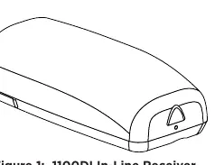
- Figure 1 illustrates the physical appearance of the 1100DI In-Line Wireless Receiver.
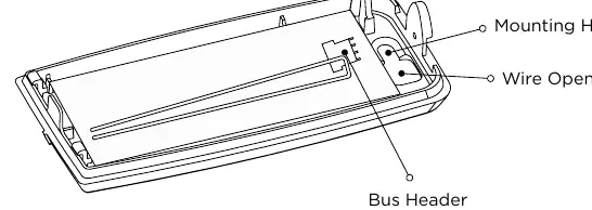
- Figure 2 details the PCB layout, showing the location of the bus header, wire opening, and mounting holes.
Model compatibility
- Compatible with XT30/XT50 Series panels.
- Requires firmware Version 102 or higher.
- Refer to DMP 1100 Series Wireless Compatibility Guide (LT-1029) for specific transmitter compatibility.

Manual page author
Michael Turner
Technical manual editor
Reviews PDF manuals for structure, safety notes, and practical product details so readers can find the right information quickly.