Electronics / Wireless Receivers
Installation Guide for DMP 1100X Series Wireless Receiver
A comprehensive installation and setup guide for the DMP 1100X Series Wireless Receiver. Includes step-by-step instructions for panel programming, device mounting, wiring, LED status interpretation, and technical specifications.
Table of contents
Manual images
Click an image to enlargeQuick Start Guide
The 1100X Series Wireless Receiver provides up to 100 wireless zones for XR150 Series panels and up to 500 wireless zones for XR550 Series panels. The 1100XE model features 128-bit AES encryption. To install, you must program the panel, select a location, mount the device, and wire it to the panel's XBUS.
Programming the Panel
Before installation, ensure the panel is programmed correctly:
- Reset the panel.
- At a keypad, enter 6653 (PROG) to access the PROGRAMMER menu.
- In SYSTEM OPTIONS, program a HOUSE CODE between 1 and 50.
- For 1100XE models: At the 1100 ENCRYPTION prompt, select ALL to add only encrypted devices, or BOTH to allow both encrypted and non-encrypted devices.
- If prompted for a passphrase, press CMD to keep the default or enter an 8-character hexadecimal string (0-9, A-F).
- Press CMD until STOP displays, then save the programming.
Selecting a Location
The receiver should be centrally located between the DMP panel and the 1100 Series transmitters. Perform an LED survey using an 1106 Series Universal Wireless Transmitter:
- Remove the transmitter cover and hold it in the desired location.
- Press the tamper switch to send data to the panel.
- Confirmed: The LED blinks immediately on and off.
- Faulty: The LED remains on for about 8 seconds or flashes multiple times. Relocate the receiver until the LED confirms clear communication.
Mounting the Receiver
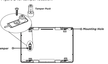
- Remove the cover from the plastic housing.
- Use the included #6 screws to secure the 1100X to the wall.
- Use one of the provided screws to secure the wall tamper.
Wiring the Receiver
The panel recognizes the 1100X automatically if the house code is programmed. Do not use shielded wire.
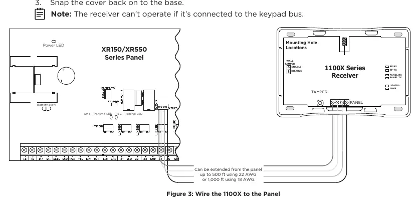
- Connect the red, yellow, green, and black wires to the PANEL terminal on the 1100X.
- Connect the other end of the wires to the XBUS on the panel.
- Snap the cover back onto the base.
- Note: The receiver cannot operate if connected to the keypad bus.
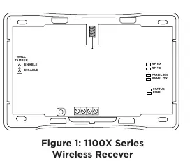
LED Indicators
The six LEDs on the PCB display receiver operation:
- RF RX: Flashing yellow indicates data is being received from a transmitter.
- RF TX: Flashing green indicates data is being sent to a transmitter.
- PANEL RX: Flashing yellow indicates data is being received from a panel.
- PANEL TX: Flashing green indicates data is being sent to the panel.
- STATUS: Solid red indicates memory is being uploaded.
- PWR: Solid green indicates power is present.
Technical Specifications
- Operating Voltage: 12 VDC Nominal.
- Current Draw: 25 mA (average), 35 mA (peak).
- Frequency Range: 905-924 MHz.
- Housing Dimensions: 5.5 inches W x 3.75 inches L x 1 inch H.
- Housing Material: Flame Retardant ABS.
Practical help
Common problems
Communication faulty during LED survey
The LED remains on for 8 seconds or flashes multiple times. Relocate the receiver until the LED confirms clear communication.
Receiver not operating
Ensure the receiver is connected to the XBUS on the panel. It cannot operate if connected to the keypad bus.
Low voltage issues
If voltage drop between the panel and device exceeds 2.0VDC, install an additional auxiliary power supply at the end of the circuit.
Before use
- Reset the panel.
- Program a House Code between 1 and 50.
- Ensure panel firmware version is 183 or higher for encryption.
- Use 18 or 22-gauge unshielded wire for connections.
- Verify the receiver is connected to the XBUS, not the keypad bus.
Specs in practice
- Operating Voltage
- 12 VDC Nominal.
- Frequency Range
- 905-924 MHz.
- Max Wire Distance
- 2,500 feet total circuit length (all branches combined).
- Current Draw
- 25 mA average, 35 mA peak.
Images and diagrams
- Figure 1: Overview of the 1100X Series Wireless Receiver showing LED locations and tamper switch.
- Figure 2: Inside the 1100X housing, identifying mounting holes and the wall tamper location.
- Figure 3: Wiring diagram showing connections between the 1100X Receiver and the XR150/XR550 Series Panel.
Model compatibility
- Compatible with XR150/XR550 Series Panels.
- 1100T Translator requires receiver firmware version 207/301 or higher.

Manual page author
Emily Carter
User documentation editor
Prepares concise manual descriptions and highlights the most useful setup, operation, and maintenance information for readers.