Electronics / Wireless Receivers
Installation Guide for DMP 1100DH Wireless Receiver
Learn how to install and configure the DMP 1100DH High Power Wireless Receiver. This guide covers panel programming, wiring, mounting, LED diagnostics, and system compatibility for XT30/XT50 panels.
Table of contents
Manual images
Click an image to enlargeQuick Guide from the Manual
The 1100DH Series Wireless Receiver provides up to 32 wireless zones for DMP XT30/XT50 Series panels. It utilizes 900 MHz frequency hopping spread spectrum technology for two-way, supervised communication. The system is designed for one 1100DH receiver per panel. Installation involves programming the panel, selecting a location using an LED survey, and wiring the receiver to the panel's keypad bus.
Compatibility
The 1100DH is compatible with the following systems and requirements:
- XT30 Series panels
- XT50 Series panels running firmware Version 102 or higher
- Encryption: Requires panel Version 183 or higher
- 1100T Translator: Requires receiver firmware Version 207/301 or higher
Programming the Panel
Refer to the panel programming guide for detailed steps. Follow this sequence:
- Reset the panel.
- Access the PROGRAMMER menu by entering 6653 (PROG) at a keypad.
- In SYSTEM OPTIONS, program a HOUSE CODE between 1 and 50.
- For XT50 panels, select NO at the BUILT IN 1100 WIRELESS prompt to enable the 1100DH.
- For 1100DHE models, select ALL or BOTH at the 1100 ENCRYPTION prompt.
- Set the passphrase if required (8-character hexadecimal string).
- Press CMD until STOP displays, then save and exit.
Selecting a Location
The receiver should be centrally located between the DMP panel and the 1100 Series transmitters. Use an 1106 Series Universal Wireless Transmitter to perform an LED survey:
- Remove the cover and hold the transmitter in the desired location.
- Press the tamper switch to send data to the panel.
- Confirmed: The LED blinks immediately on and off for each press/release.
- Faulty: The LED remains on for about 8 seconds or flashes multiple times. Relocate the receiver until the LED confirms clear communication.
Wiring and Mounting
Do not use shielded wire between the panel and receiver. Use 18 or 22-gauge unshielded wire.
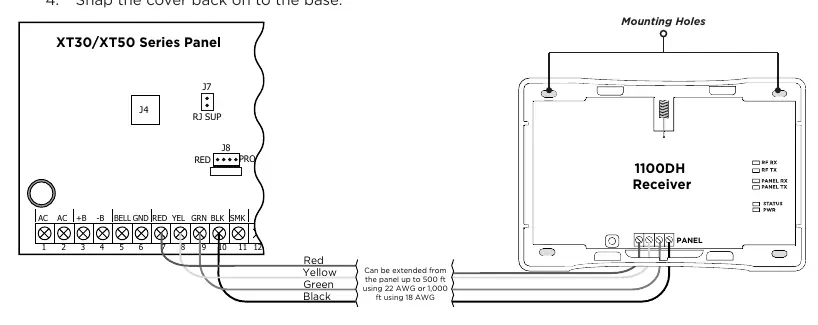
- Connect the red, yellow, green, and black wires to the PANEL terminal on the 1100DH.
- Connect the other end of the wires to terminals 7, 8, 9, and 10 on the panel.
- Secure the 1100DH to the surface using the included #6 screws.
- Snap the cover back onto the base.
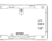
LED Operation
The six labeled LEDs on the PCB display receiver activity:
- RF RX: Flashing yellow indicates data is being received from a transmitter.
- RF TX: Flashing green indicates data is being sent to a transmitter.
- PANEL RX: Flashing yellow indicates data is being received from a panel.
- PANEL TX: Flashing green indicates data is being sent to the panel.
- STATUS: Solid red indicates memory is being uploaded.
- PWR: Solid green indicates power to the receiver.
Specifications
- Operating Voltage: 12 VDC Nominal
- Current Draw: 75 mA (average), 102 mA (peak)
- Frequency Range: 905-924 MHz
- Housing Dimensions: 5.5 inches W x 3.75 inches L x 1 inch H
- Housing Material: Flame Retardant ABS
Practical help
Common problems
Communication faulty during LED survey
The LED remains on for 8 seconds or flashes rapidly. Relocate the receiver until the LED confirms clear communication.
Voltage drop on circuit
If voltage at any device is less than 2.0VDC, add an auxiliary power supply at the end of the circuit.
Encryption not working
Ensure the panel is running version 183 or higher.
Before use
- Verify panel compatibility (XT30/XT50 series).
- Ensure panel firmware is version 102 or higher.
- Use 18 or 22-gauge unshielded wire (do not use twisted pair or shielded wire).
- Confirm house code (1-50) is ready for programming.
- Ensure total wire length does not exceed 2,500 feet.
Specs in practice
- Operating Voltage
- 12 VDC Nominal.
- Frequency Range
- 905-924 MHz.
- Max Wire Distance
- 2,500 feet total circuit length regardless of wire gauge.
- Current Draw
- 75 mA average, 102 mA peak.
Images and diagrams
- Figure 1 shows the receiver layout and LED indicators.
- Figure 2 illustrates the wiring connection from the receiver to the panel terminals 7, 8, 9, and 10.
Model compatibility
- Compatible with XT30 and XT50 series panels.
- Encryption requires panel version 183 or higher.
- 1100T Translator requires receiver firmware 207/301 or higher.

Manual page author
Emily Carter
User documentation editor
Prepares concise manual descriptions and highlights the most useful setup, operation, and maintenance information for readers.