Toys / RC Models & Drones
User Manual for E-flite Extra 300 1.3m RC Airplane
Comprehensive user guide for the E-flite Extra 300 1.3m RC airplane. Includes assembly instructions, SAFE Select and AS3X setup, binding procedures, battery installation, and troubleshooting tips.
Table of contents
Manual images
Click an image to enlargeQuick guide from the manual
The E-flite Extra 300 1.3m is a high-performance RC airplane featuring SAFE Select and AS3X technologies. Before your first flight, ensure the battery is fully charged, the transmitter is set up according to the provided chart, and the Center of Gravity (CG) is correctly balanced. Always perform a range test and control direction test before flying.
Model Assembly
Landing Gear Installation
Fit the landing gear into the slot on the fuselage. Secure the landing gear cover using four 3 x 15mm screws.
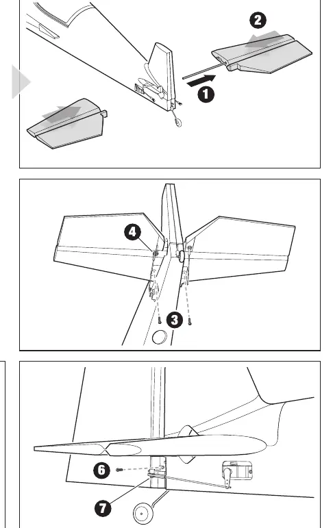
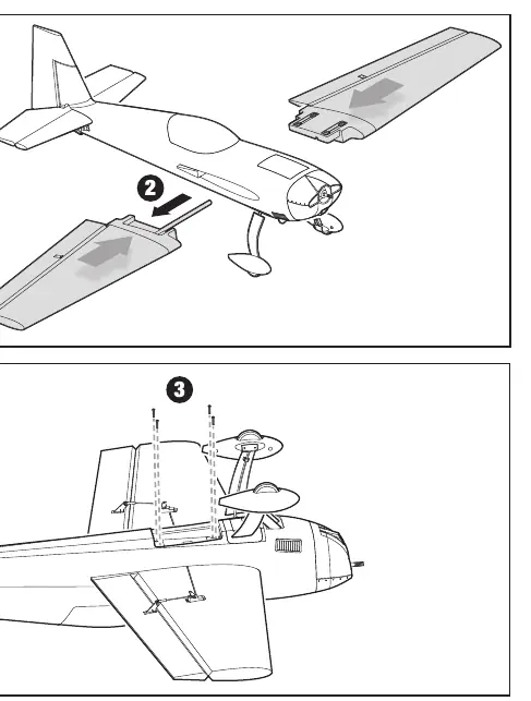
Tail Installation
Insert the horizontal stabilizer tube into one of the stabilizer halves, then slide the halves together into the fuselage. Secure with two 3 x 15mm screws. Connect the Z-bend of the pushrod to the elevator servo arm and control horn. For the vertical fin, apply epoxy or medium/thick CA glue to the rudder hinge tabs, slide into the hinge slot, and secure the tail wire bracket with 2 x 8mm flat head screws.
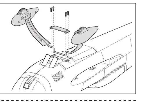
Wing Installation
Remove the magnetic bottom hatch cover. Slide the wing joiner into one wing panel, insert into the fuselage, and attach the other wing panel. Route aileron servo leads inside the wing saddle and out the bottom hatch. Secure the wing panels to the fuselage using four 3 x 30mm screws.
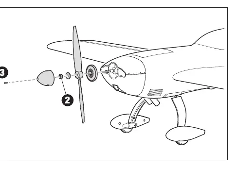
Propeller Installation
Install the spinner back plate, propeller, prop washer, and prop nut onto the motor shaft. Tighten the nut securely and attach the spinner with the 3 x 15mm screw.
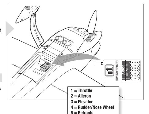
Receiver Installation
The Spektrum AR631 receiver is recommended. Mount the receiver parallel to the length of the fuselage using hook and loop material. Connect ESC and servo leads to the appropriate ports: 1=Throttle, 2=Aileron, 3=Elevator, 4=Rudder/Nose Wheel, 5=Retracts, 6=Flaps. Use the included Y-Harness for the two aileron servos.
Transmitter Setup and Binding
Ensure your transmitter is programmed with the recommended dual rates and expo settings. To bind, install the bind plug in the receiver, connect the flight battery, and power on the transmitter while holding the bind button. The receiver is bound when the orange LED stays solid.
SAFE Select and AS3X
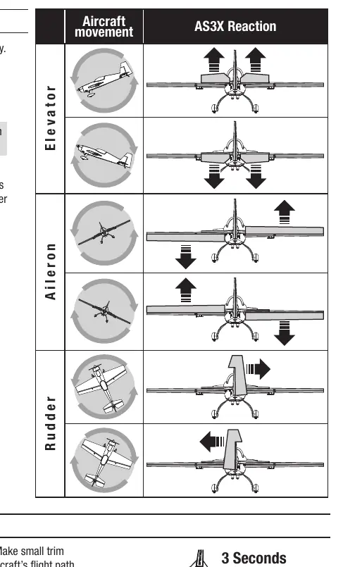
SAFE Select provides flight envelope protection and can be assigned to a switch on your transmitter. AS3X technology provides stabilization. Always perform the AS3X Control Direction Test by raising the throttle above 25% to activate the system, then moving the aircraft to ensure control surfaces react in the correct direction.
Battery Installation
Use a 14.8V 4S 2200-3200mAh Li-Po battery. Apply hook and loop tape to the battery and tray, secure with straps, and connect to the ESC. Ensure the aircraft remains immobile on a flat surface during initialization.
Flying Tips and Maintenance
Always take off into the wind. Use the recommended flight timer of 3 minutes for initial flights. After flying, disconnect the battery to prevent over-discharge. Repairs to the EPO foam can be made using standard adhesives like CA, epoxy, or hot glue.
Manufacturer information
E-flite
Practical help
Common problems
Aircraft will not bind to transmitter
Move the transmitter further away from the aircraft, ensure the bind plug is installed correctly, and check that the flight battery is fully charged.
Oscillation during flight
Balance the propeller, check for loose receiver or control surfaces, and ensure all parts are secure.
Reduced flight time or underpowered
Check battery charge, ensure the propeller is installed with numbers facing forward, and verify battery health.
Control surface does not move
Check for damaged linkages, loose connections, or re-bind the transmitter.
Before use
- Charge the flight battery fully.
- Set up transmitter using the provided setup chart.
- Check Center of Gravity (CG) at 90-100mm from the wing leading edge.
- Perform a radio system range test.
- Ensure all linkages move freely.
- Perform Control Direction Test and AS3X Control Direction Test.
Images and diagrams
- Landing gear installation: Secure with four 3x15mm screws.
- Tail installation: Horizontal stabilizer and vertical fin assembly steps.
- Wing installation: Secure panels with four 3x30mm screws.
- Receiver wiring: Port layout for throttle, aileron, elevator, rudder, retracts, and flaps.
Model compatibility
- Requires a full-range 6-channel (or more) 2.4GHz transmitter with Spektrum DSM2/DSMX technology.
- Compatible with Spektrum AR631 receiver.

Manual page author
David Miller
Documentation analyst
Organizes user manual content into clear summaries, with attention to model details, product context, and everyday usability.