Power / Batteries & Chargers
User Manual for Eco Worthy 1500W Solar Inverter Charger
Quick guide and user manual for the Eco Worthy 1500W Solar Inverter Charger. Includes installation steps, wiring diagrams, operation instructions, error code troubleshooting, and technical specifications.
Table of contents
Manual images
Click an image to enlargeQuick guide from the manual
This manual provides essential instructions for the Eco Worthy 1500W Solar Inverter Charger. It is intended for qualified personnel only. Key safety requirements include disconnecting all wiring before maintenance, avoiding metal tools near batteries to prevent short circuits, and ensuring the battery bank voltage remains below 30V DC.
Introduction
The 1500W Solar Inverter Charger is a multi-function device combining a DC-AC off-grid inverter and a solar charge controller. Key features include high-frequency digital control, pure sine wave output, an integrated solar charge controller, an LCD display for monitoring, and smart fan control for noise reduction and longevity.
Installation
Before installation, inspect the unit for damage. Choose a solid wall for mounting, ensuring the unit is at eye level for easy display reading. The ambient temperature must be between 0 and 40°C. Ensure sufficient space around the unit for heat dissipation.
Wiring and Connections:
- Battery Connection: Connect the positive pole through a breaker (100A fuse recommended) and the negative pole directly to the battery. Ensure the battery bank voltage is below 30V DC.
- PV Connection: It is recommended to install a DC breaker between the PV modules and the inverter. Ensure the total PV input voltage is below 75V DC.
- AC Output Connection: It is recommended to install an AC breaker between the inverter and the load.
All wiring must be performed by professionals using the recommended cable sizes (10AWG for battery and PV, 14AWG for AC output).
Operation
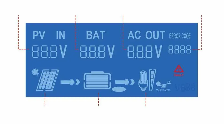
Once installed, press the POWER ON/OFF button on the panel. The LCD will light up, and after a few seconds, the BAT and AC OUT indicators will appear, signaling the inverter has started. The LCD displays PV voltage, battery voltage, AC output voltage, and working status. Icons indicate power flow, battery power levels, and load capacity.
Troubleshooting
The unit displays error codes to indicate faults. If multiple faults occur, the code will flash in a cycle. Common issues include battery over/under-voltage, cooling fan over-temperature, PV input over-voltage, and AC output overload. Refer to the error code table in the manual for specific corrective actions, such as reducing the load or checking cooling conditions.
Technical Specifications
The inverter supports a battery voltage range of 19.5-30V DC and provides a 120VAC pure sine wave output at 60Hz. The rated output power is 1500W. The PV input voltage range is 10-80V DC. The unit features comprehensive protection, including reverse-polarity, short-circuit, over-temperature, and over-current protection.
Manufacturer information
ECO-WORTHY
Practical help
Common problems
Battery over-voltage (Error 1)
Check if battery input voltage exceeds 30V DC or if there is an external charging input.
Battery under-voltage (Error 2)
Reduce or turn off the load to allow the battery to charge.
Cooling fan over-temperature (Error 3)
Check surrounding cooling conditions and ensure the fan is running normally.
PV input over-voltage (Error 4)
Check if PV input voltage exceeds 80V DC.
AC output overload (Error 8)
Confirm if the load is too high and reduce the load power.
Before use
- Ensure installation is performed by qualified personnel.
- Verify the battery bank voltage is below 30V DC.
- Verify the total PV input voltage is below 75V DC.
- Install a DC breaker for the battery connection (100A fuse recommended).
- Install a DC breaker between PV modules and the inverter.
- Use recommended cable sizes (10AWG for battery/PV, 14AWG for AC output).
Specs in practice
- Rated Output Power
- 1500W maximum continuous power output.
- Battery Voltage Range
- 19.5-30V DC; must not exceed 30V.
- PV Input Voltage Range
- 10-80V DC; operating range is 10-75V DC.
- Output Wave Type
- Pure sine wave, suitable for sensitive electronics.
Images and diagrams
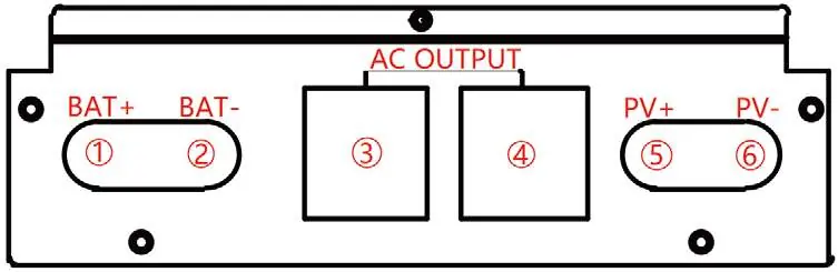
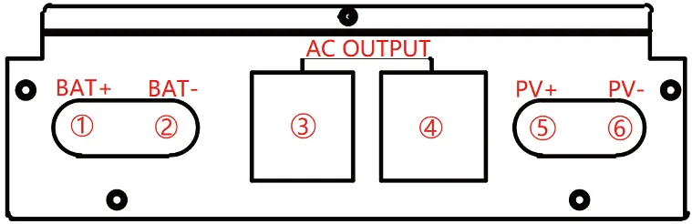
- Interface Diagram: Identifies battery terminals (1, 2), AC output ports (3, 4), and PV input terminals (5, 6).
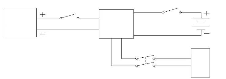
- Installation Diagram: Illustrates the connection flow from PV modules and batteries through breakers to the hybrid inverter.
Model compatibility
- Compatible with 24VDC lead-acid or lithium battery banks.
- Not compatible with battery banks exceeding 30V DC.

Manual page author
Emily Carter
User documentation editor
Prepares concise manual descriptions and highlights the most useful setup, operation, and maintenance information for readers.