Power / Batteries & Chargers
User Manual for ECO-WORTHY Dual-Axis Solar Tracker
Quick guide for the ECO-WORTHY Dual-Axis Solar Tracker. Includes installation steps, component list, wiring instructions, and sensor setup.
Quick answers from the manual
Quick answer
- The ECO-WORTHY Dual-Axis Solar Tracker is designed to hold 4-6 solar panels, automatically adjusting their angle for optimal sunlight absorption. It requires a 12V battery for the controller. p. 3, 10
Key actions
- Install the main pole using an impact drill (12mm diameter, 55mm depth). p. 7
- Connect the drive rods, sensors, and 12V battery to the controller. p. 10
- Mount the solar panels using the provided clamps. p. 11
First start
- Connect the 12V battery to the fourth port on the controller to power the system. p. 10
Problems and fixes
System not operating
Check all cable connections to the controller, specifically the 12V battery input.
p. 10Technical specifications
| Parameter | Value | Meaning | Pages |
|---|---|---|---|
| Panel Capacity | 4-6 panels (max 4*200W) | Maximum load capacity | p. 12 |
Where to find it in the PDF
- Installation Guide p. 5, 6, 7, 8
Table of contents
Manual images
Click an image to enlargeQuick guide from the manual
The ECO-WORTHY Dual-Axis Solar Tracker is designed to hold 4-6 solar panels, allowing them to track the sun for increased energy absorption. The system requires a 12V battery for the controller to operate. Before proceeding, ensure the mounting surface is strong enough to support the weight of the tracker and panels. Regularly check the system for wear or corrosion.
Components
The package includes the following items:
- Main pole
- White rods (B, C, D, E)
- Mounting rods (G)
- Drive rods
- Controller
- Sunshine sensor
- Air speed sensor
- Various nuts, bolts, and connectors
Installation
1. Place the main pole: Identify the N, S, W, E marks on the pole and align them with the corresponding directions. Drill a hole with a 12mm diameter and 55mm depth, then secure the pole using M10x60 expansion screws.
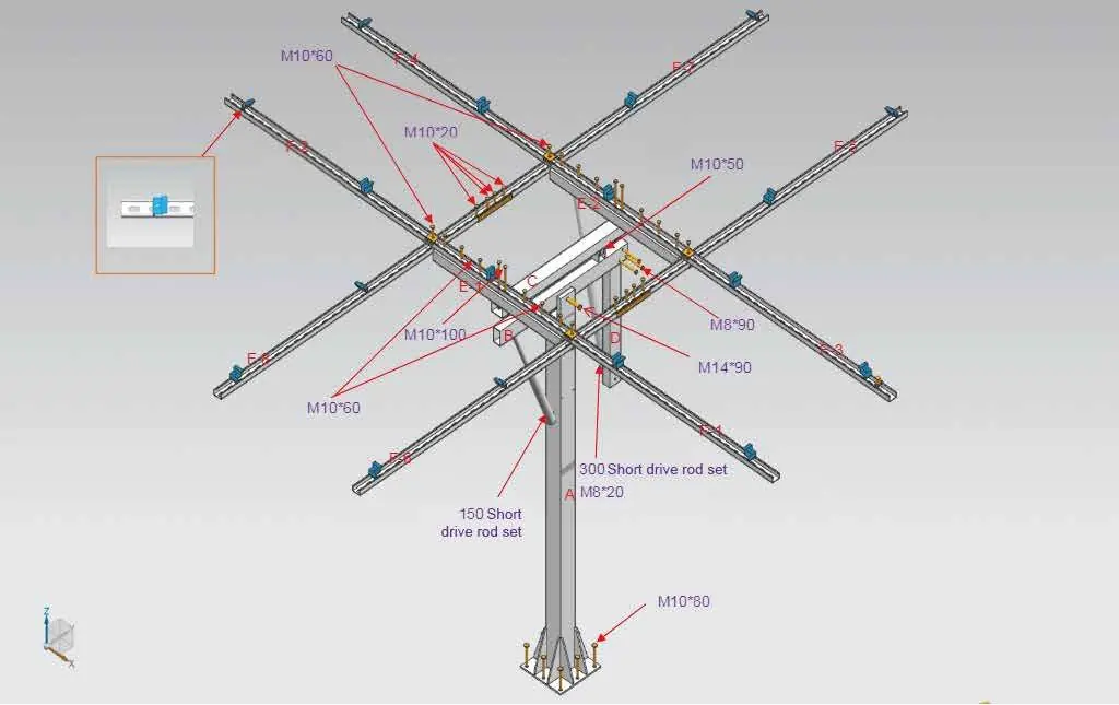
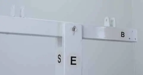
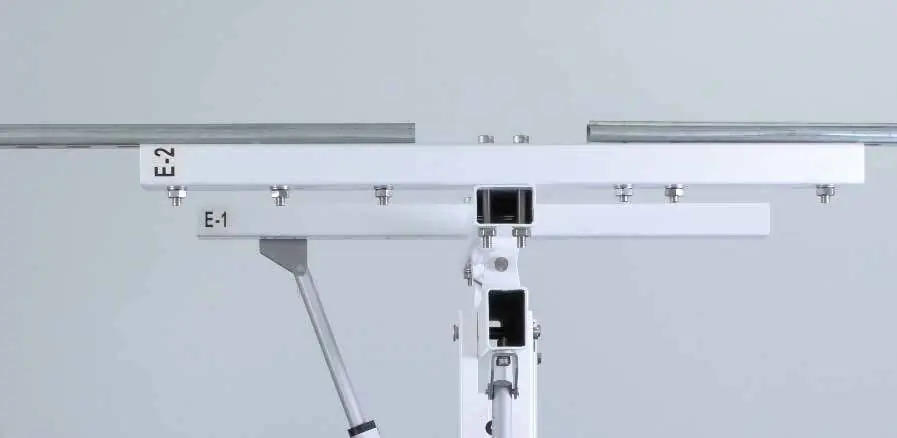
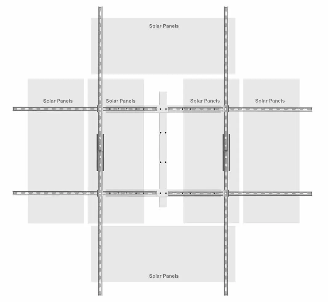
2. Assemble the rods: Attach the B rod to the main pole using the M14*90 latch. Connect the C rod to the B rod using M10*50 latches. Fix the D rod to the B rod using M8*90 screws (ensure a 90-degree angle). Attach E-1 and E-2 rods to the C rod using M10*100 screws.
3. Install drive rods: Fix the drive rod bases to the S side of the main rod and the underside of the B rod using M8*20 screws. Attach the short and long drive rods to these bases.
4. Mount the solar panels: Use the provided clamps to secure the panels to the bracket. Use the double-head middle clamp between two panels and the side clamp for the outer edges.
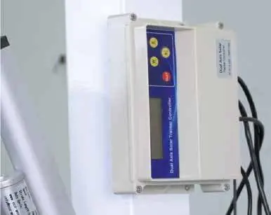
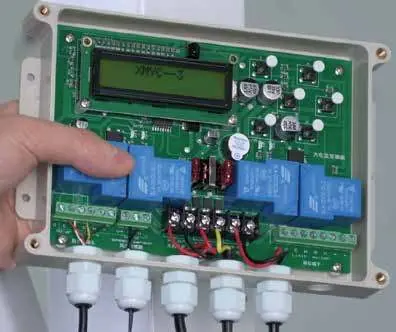
Wiring
Open the controller cover to access the circuit board. Connect the drive rod cables to the third and fifth ports. Connect the air speed sensor to the second port (match G and IN labels). Connect a 12V battery to the fourth port to power the system. Secure the cover after wiring.
Support
If you experience technical issues, please contact ECO-WORTHY support:
US: 1-866-939-8222UK: +44 20 7570 0328Email: [email protected]
Manufacturer information
ECO-WORTHY
Practical help
Common problems
Tracker not moving
Check the 12V battery connection to the fourth port on the controller.
Sensor not detecting sunlight
Ensure the sunshine sensor is fixed on the top right corner of the bracket.
Wind sensor not working
Ensure the sensor is placed in an area with good ventilation and no obstructions.
Before use
- Verify the mounting surface can support the weight of the tracker and panels.
- Ensure all components (rods, sensors, controller) are present.
- Have an impact drill (12mm bit) and screwdriver ready.
- Ensure a 12V battery is available for the controller.
Specs in practice
- Panel Capacity
- Supports 4-6 solar panels (max 4*200W).
- Drilling requirements
- Requires 12mm diameter, 55mm depth for main pole installation.
- Controller power
- Requires a 12V battery connection.
Images and diagrams
- The manual includes a detailed exploded view of the assembly on page 7.
- Wiring diagrams for the controller are provided on page 10.
Model compatibility
- Designed for 4-6 solar panels.
- Requires 12V battery for operation.

Manual page author
Emily Carter
User documentation editor
Prepares concise manual descriptions and highlights the most useful setup, operation, and maintenance information for readers.