HVAC / Thermostats & Controls
Emerson 1F85U-42NP Non-Programmable Thermostat Installation and Operating Instructions
Quick guide for the Emerson 1F85U-42NP non-programmable thermostat. Includes installation, wiring, configuration, troubleshooting, and operating instructions.
Quick answers from the manual
Quick answer
- The Emerson 1F85U-42NP is a non-programmable universal thermostat. Installation requires wiring to the appropriate terminals (RC, RH, Y, G, W/E, C, L, Y2, W2). Configuration is managed via the Installer Menu (accessed by holding the Menu button for 8 seconds). p. 1, 2, 3
Key actions
- Access Installer Menu p. 3
- Reset to Factory Defaults p. 8
First start
- Turn on power to the system and test fan, heating, and cooling operations. p. 4
Problems and fixes
No Heat/Cool/Fan
Check fuse/breaker, power switch, furnace door panel, and wiring connections.
p. 7Maintenance and reset
- Reset thermostat by removing batteries for 2 minutes or using the Menu + Backlight button combination. p. 8
Technical specifications
| Parameter | Value | Meaning | Pages |
|---|---|---|---|
| Electrical Rating | mV to 30 VAC | Operating voltage range | p. 1 |
| Setpoint Range | 45° to 99° F | Temperature control range | p. 1 |
Where to find it in the PDF
- Specifications and Index p. 1
- Installation and Wiring p. 2
- Installer Menu p. 3, 4
- Thermostat Overview p. 5
- User Menu and Operation p. 6
- Troubleshooting p. 7, 8
Table of contents
Manual images
Click an image to enlargeQuick Guide
The Emerson 1F85U-42NP is a non-programmable universal thermostat designed for conventional gas, oil, electric, and heat pump systems. Key operations include accessing the Installer Menu by holding the Menu button for 8 seconds and resetting the device by holding the Menu and Backlight buttons simultaneously.
Installation and Wiring
Before installation, ensure the power is disconnected at the main fuse or circuit breaker box. The thermostat is compatible with 24V systems. Wiring must conform to local and national electrical codes.
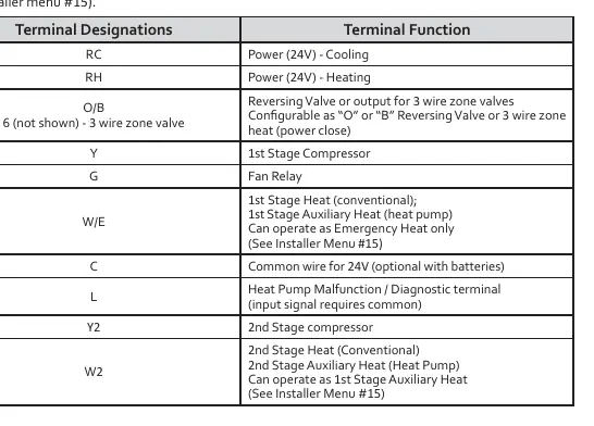
- RC: Power (24V) - Cooling
- RH: Power (24V) - Heating
- O/B: Reversing Valve or 3-wire zone valve
- Y: 1st Stage Compressor
- G: Fan Relay
- W/E: 1st Stage Heat (conventional) / 1st Stage Auxiliary Heat (heat pump)
- C: Common wire for 24V (optional with batteries)
- L: Heat Pump Malfunction / Diagnostic terminal
- Y2: 2nd Stage Compressor
- W2: 2nd Stage Heat (conventional) / 2nd Stage Auxiliary Heat (heat pump)
Note: The thermostat connects RC and RH internally; if your application requires separate wires, clip the RC/RH jumper wire.
Installer Menu Configuration
To access the Installer Menu, press and hold the Menu button for 8 seconds. Use Next and Back to navigate, and the arrow buttons to change settings.
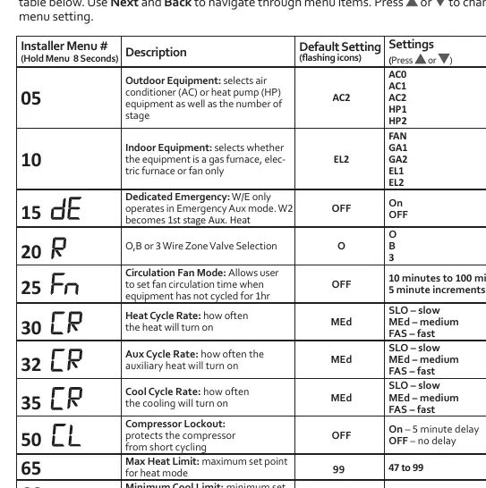
- 05: Outdoor Equipment (AC/HP selection)
- 10: Indoor Equipment (Gas/Electric/Fan)
- 15: Dedicated Emergency Heat
- 20: O/B or 3-Wire Zone Valve Selection
- 30/32/35: Cycle Rates (Heat/Aux/Cool)
- 50: Compressor Lockout (prevents short cycling)
- 65/66: Max Heat / Min Cool Limits
- 79: Fahrenheit or Celsius
- 99: Keypad Lock
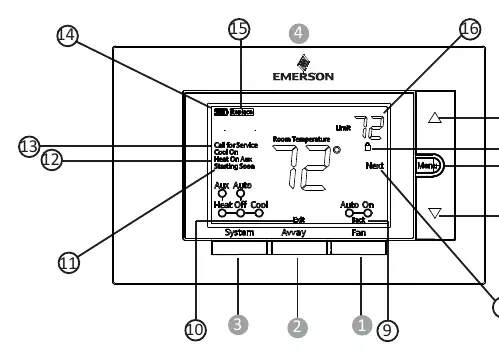
Operating the Thermostat
The thermostat features a display showing temperature, system status, and battery indicators. The Away button allows you to store a frequently used temperature setting. To set it, adjust the temperature to your desired level and hold the Away button for 3 seconds.
Troubleshooting
If you encounter issues, check the following:
- No Heat/Cool/Fan: Check for blown fuses, tripped breakers, or loose wiring. Ensure the furnace door panel is properly installed.
- "Call for Service" icon: Indicates the system cannot reach the setpoint within 2 hours or a self-diagnostic issue. Contact a service person.
- Display blank: Replace batteries.
- Resetting: To reset the thermostat, remove batteries for 2 minutes. To reset to factory defaults, hold the Menu and Backlight buttons simultaneously until the display resets.
Practical help
Common problems
No Heat/Cool/Fan
Check for blown fuses, tripped circuit breakers, ensure the furnace power switch is ON, and verify that the furnace blower door panel is properly closed.
"Call for Service" icon appears
The system may be unable to reach the setpoint within 2 hours. Check for system issues or contact a service person if the icon is flashing.
Thermostat display is blank
Ensure batteries are installed correctly or replace them with new premium AA alkaline batteries.
Furnace cycles too fast or slow
Adjust the cycle rate in the Installer Menu (items 30, 32, and 35) to SLO (slow) for longer cycles.
Before use
- Ensure power is disconnected at the main breaker before starting installation.
- Verify system compatibility (Conventional Gas, Oil, Electric, or Heat Pump).
- Check if a C-wire is available for continuous power (optional if using batteries).
- Level the thermostat on the wall (for appearance only).
- Install premium AA alkaline batteries if not using a hardwired C-wire.
Specs in practice
- Electrical Rating
- Supports mV to 30 VAC, NEC Class II, 50/60 Hz.
- Terminal Load
- 1.5 A per terminal, 2.5A maximum for all terminals combined.
- Setpoint Range
- Adjustable from 45° to 99° F (7° to 37° C).
- Operating Humidity
- 90% non-condensing maximum.
Images and diagrams
- Wiring terminal designations and functions for various system configurations.
- Installer Menu table for configuring system parameters.
- Thermostat display and button layout overview.
Model compatibility
- Compatible with Conventional Gas, Oil, Electric (mV and 24V) systems.
- Compatible with Heat Pump (Air Source or Geothermal) with Aux. Heat.
- Requires C-wire for continuous display backlight.

Manual page author
David Miller
Documentation analyst
Organizes user manual content into clear summaries, with attention to model details, product context, and everyday usability.