HVAC / Thermostats & Controls
Installation and Operating Instructions for Emerson 1F85U-42PR Programmable Thermostat
A comprehensive guide for the Emerson 1F85U-42PR programmable thermostat. Includes installation, wiring, installer menu settings, programming, and troubleshooting steps.
Quick answers from the manual
Quick answer
- To access the Installer Menu, press and hold the Menu button for 8 seconds. Use the Next and Back buttons to navigate through menu items and the arrow buttons to change settings. p. 2, 6, 10
Key actions
- Programming the schedule p. 4, 7, 12
- Resetting the thermostat p. 4, 7, 8, 12
First start
- Set current time and day p. 3, 7, 11
Problems and fixes
No Heat
Set thermostat to Heat, verify wires are attached, perform diagnostic by raising setpoint above room temp.
p. 4, 7, 8, 12Maintenance and reset
- Resetting to factory defaults p. 4, 7, 8, 12
Technical specifications
| Parameter | Value | Meaning | Pages |
|---|---|---|---|
| Electrical Rating | mV to 30 VAC, NEC Class II, 50/60 Hz | Power requirements for the thermostat. | p. 1, 5, 9 |
Where to find it in the PDF
- Installation and Wiring p. 1, 2, 5, 9
- Installer Menu p. 2, 3, 6, 10
- User Menu and Operation p. 3, 7, 11
- Troubleshooting p. 4, 7, 8, 12
Table of contents
Manual images
Click an image to enlargeQuick Guide
This guide covers the installation and operation of the Emerson 80 Series Universal Thermostat (Model 1F85U-42PR). Key features include battery or hardwired power, 5-1-1 or 7-day programming, and compressor protection. For technical support, contact the Homeowner Help Line at 1-800-284-2925.
Installation and Wiring
Precautions: Ensure all wiring conforms to local and national electrical codes. Disconnect power at the main fuse or circuit breaker box before installation. Do not exceed specified voltage ratings.
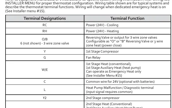
Wiring Terminals:
- RC: Power (24V) - Cooling
- RH: Power (24V) - Heating
- O/B: Reversing Valve or 3-wire zone valve
- Y: 1st Stage Compressor
- G: Fan Relay
- W/E: 1st Stage Heat (conventional) / Auxiliary Heat (heat pump)
- C: Common wire for 24V (optional with batteries)
- L: Heat Pump Malfunction / Diagnostic terminal
- Y2: 2nd Stage Compressor
- W2: 2nd Stage Heat (Conventional) / 2nd Stage Auxiliary Heat (Heat Pump)
Installer Menu
To access the Installer Menu, press the Menu button for 8 seconds. Use Next and Back to navigate, and the arrow buttons to change settings.
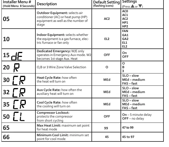
- 05 Outdoor Equipment: Select AC or Heat Pump and number of stages.
- 10 Indoor Equipment: Select furnace type (Gas, Electric, Fan only).
- 15 Dedicated Emergency: Configure W/E for Emergency Aux mode.
- 30/32/35 Cycle Rates: Adjust heating, auxiliary, and cooling cycle rates (Slow, Medium, Fast).
- 50 Compressor Lockout: Enable/disable 5-minute delay to protect the compressor.
- 99 Keypad Lock: Enable/disable button locking.
User Menu
Press the Menu button to access user settings:
- 01 Schedule Type: 7-Day, 5-1-1 Day, or Non-Programmable.
- 02 Periods per Day: 2 or 4 periods.
- 04 Fahrenheit/Celsius: Toggle temperature display.
- 07 Change Air Filter: Set monthly reminder (1-12 months).
Operation
Setting Time and Day: Press Menu, then use Next to advance to time/day settings. Use arrows to adjust and Exit to finish.
Programming: Use the System button to select Heat or Cool, then Menu to access the Schedule. Follow the on-screen prompts to set times and temperatures for Wake, Leave, Return, and Sleep periods.
Hold/Override: Press Hold/Run to maintain a permanent temperature. Press arrow buttons to temporarily override the schedule until the next period.
Troubleshooting
If the display is blank or unresponsive, remove batteries for 2 minutes to reset. For "Call for Service" icons, check if the system can reach the setpoint within 2 hours or if the compressor diagnostic is triggered. Ensure the keypad lock is not active if buttons are unresponsive.
Specifications
- Electrical Rating: mV to 30 VAC, NEC Class II, 50/60 Hz.
- Setpoint Range: 45° to 99° F (7° to 37° C).
- Operating Ambient: 32°F to +105°F (0° to +41°C).
- Operating Humidity: 90% non-condensing maximum.
Practical help
Common problems
No Heat/No Cool/No Fan
Check for blown fuse/tripped breaker, ensure furnace power switch is ON, check if furnace blower door is properly installed, and verify wire connections.
Compressor won't start immediately
The thermostat has a 5-minute compressor lockout feature to prevent short cycling. Wait 5 minutes.
Call for Service icon displayed
Check if the system can heat/cool the space within 2 hours. If flashing, the compressor self-diagnostic may have detected an issue with the outdoor unit.
Before use
- Verify thermostat and system wires are securely attached.
- Ensure batteries are installed if C-wire is not available.
- Set the system switch to Heat or Cool.
- Check that the furnace power switch is ON.
- Ensure the furnace blower compartment door is closed.
Specs in practice
- Setpoint Range
- The temperature range the thermostat can be set to (45°F to 99°F).
- Compressor Lockout
- A 5-minute delay to protect the compressor from short cycling.
- Terminal Load
- 1.5 A per terminal, 2.5A maximum for all terminals combined.
Images and diagrams
- The wiring table on page 1 defines terminal functions (RC, RH, Y, G, W/E, etc.).
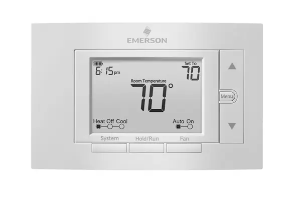
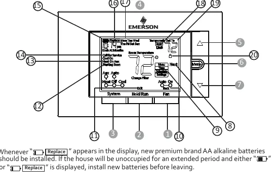
- The thermostat display shows battery status, temperature setpoint, and system mode (Heat/Cool/Aux).
Model compatibility
- Compatible with conventional gas, oil, electric systems (mV and 24V).
- Compatible with heat pumps (air source or geothermal) with auxiliary heat.
- Requires C-wire for continuous display light.

Manual page author
Michael Turner
Technical manual editor
Reviews PDF manuals for structure, safety notes, and practical product details so readers can find the right information quickly.