HVAC / Thermostats & Controls
Emerson 1F83H-21NP Thermostat User Manual
Comprehensive user guide for the Emerson 1F83H-21NP non-programmable heat pump thermostat. Includes installation instructions, wiring diagrams, installer menu settings, operation, and troubleshooting.
Quick answers from the manual
Quick answer
- The Emerson 1F83H-21NP is a non-programmable heat pump thermostat. It supports 24V AC power (hardwired or battery) and includes an installer menu for configuring cycle rates and system parameters. p. 1
Key actions
- Access Installer Menu p. 3
- Reset Thermostat p. 8
First start
- Wiring and Power p. 2, 3
Problems and fixes
Heating/Cooling not working
Check circuit breaker, furnace switch, and wiring connections.
p. 7Maintenance and reset
- Reset to defaults p. 8
Technical specifications
| Parameter | Value | Meaning | Pages |
|---|---|---|---|
| Voltage | 20-30V AC | Power supply requirements | p. 1 |
| Dimensions | 3-3/4" H x 6" W x 1-1/8" D | Physical size | p. 1 |
Where to find it in the PDF
- Specifications p. 1
- Installer Menu p. 3, 4
- Troubleshooting p. 7, 8
Table of contents
Manual images
Click an image to enlargeQuick Guide from the Manual
The Emerson 1F83H-21NP is a non-programmable heat pump thermostat designed for single-stage compressor systems with auxiliary/emergency heat. It supports battery or hardwired power (24V). To access the Installer Menu, press and hold the Menu button for 8 seconds.
Installation and Wiring
Ensure power is turned off at the main circuit breaker before installation. The thermostat requires 24V AC power. If a common wire (C) is not available, AA batteries are required.
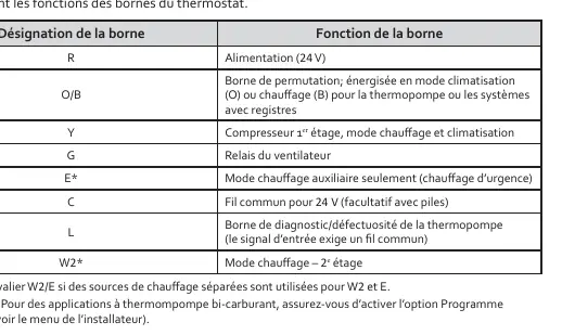
- R: 24V Power
- O/B: Reversing valve (energized in Cool or Heat mode)
- Y: 1st Stage Compressor
- G: Fan Relay
- E: Auxiliary/Emergency Heat
- C: Common wire (optional with batteries)
- L: Diagnostic/Fault terminal
- W2: 2nd Stage Heat
Installer Menu
To access, press the Menu button for 8 seconds. Use Next to navigate and the arrow buttons to change settings.
- 30: Heating cycle rate (SLO/MED/FAS)
- 32: Auxiliary heat cycle rate
- 35: Cooling cycle rate
- 50: Compressor lockout (protects against short cycling)
- 60: Dual fuel program (Gas/Electric auxiliary heat)
- 65/66: Temperature setpoint limits
- 79: Fahrenheit/Celsius selection
- 83: Continuous backlight
- 99: Keypad lockout
Operation
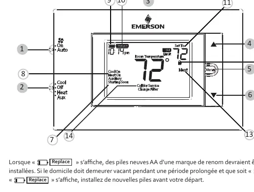
The thermostat features a display showing room temperature, setpoint, and system status (Heat On, Cool On, Auxiliary). The backlight button is located on the top of the unit. If the "Replace" icon appears, replace the AA batteries.
Troubleshooting
- Heating/Cooling not working: Check circuit breakers, furnace power switch, and wiring connections.
- Call for Service icon: Indicates the system cannot reach the setpoint within 2 hours or the compressor self-diagnostic has detected a fault.
- Display blank/unresponsive: Check batteries or reset the thermostat by removing batteries for 2 minutes.
- Resetting: To reset the schedule and settings to default, press the Menu and Backlight buttons simultaneously until the display clears.
Practical help
Common problems
Heating or cooling not functioning
Check if the circuit breaker is tripped, the furnace switch is ON, and wiring connections are secure.
Call for Service icon appears
The system failed to reach the setpoint within 2 hours or a compressor fault was detected. Contact a technician.
Thermostat unresponsive or blank display
Check batteries. If they are good, reset the thermostat by removing batteries for 2 minutes.
Before use
- Turn off power at the main circuit breaker.
- Verify wiring matches system requirements.
- Install quality AA batteries if a common wire (C) is not used.
- Level the thermostat (aesthetic only).
Specs in practice
- Operating Temperature
- 32°F to +105°F (0°C to +41°C).
- Terminal Load
- 1.5A per terminal, 2.5A maximum combined.
Images and diagrams
- Wiring terminal functions table.
- Installer menu settings table.
- Thermostat display and button layout.
Model compatibility
- Designed for single-stage heat pump systems.
- Supports 1 stage of auxiliary/emergency heat.
- Not compatible with line voltage systems.

Manual page author
David Miller
Documentation analyst
Organizes user manual content into clear summaries, with attention to model details, product context, and everyday usability.