HVAC / Thermostats & Controls
Installation and User Manual for Emerson 1F83C-11PR Programmable Thermostat
Quick guide for the Emerson 1F83C-11PR programmable thermostat. Includes installation steps, wiring diagrams, installer menu settings, programming instructions, and troubleshooting.
Quick answers from the manual
Quick answer
- The Emerson 1F83C-11PR is a programmable thermostat for single-stage heating and cooling systems. It supports battery or hardwired power and features an installer menu for system configuration. p. 1
Key actions
- Access Installer Menu p. 3, 11
- Access User Menu p. 6, 14
- Reset Thermostat p. 8, 16
First start
- Install batteries, mount the thermostat, turn on system power, and set the time/day. p. 2, 6
Problems and fixes
No Heat/Cool
Check fuse/breaker, ensure system switch is set correctly, check wiring.
p. 7, 8, 15, 16Maintenance and reset
- Reset thermostat by removing batteries for 2 minutes. p. 8, 16
Technical specifications
| Parameter | Value | Meaning | Pages |
|---|---|---|---|
| Electrical Rating | 20-30V AC, 50/60Hz | Power requirements | p. 1, 9 |
| Terminal Load | 1.0A per terminal | Maximum current per terminal | p. 1, 9 |
Where to find it in the PDF
- Specifications p. 1, 9
- Installer Menu p. 3, 4, 11, 12
- Troubleshooting p. 7, 8, 15, 16
Table of contents
Manual images
Click an image to enlargeQuick guide from the manual
This document provides installation and operation instructions for the Emerson 1F83C-11PR programmable thermostat. It covers wiring, system configuration via the Installer Menu, daily programming, and troubleshooting.
Installation
Before installation, disconnect power to the system. Ensure the thermostat is leveled for appearance. Wiring must conform to local codes. Premium AA alkaline batteries are required if a C-wire is not available.
Wiring
Terminal designations and functions:
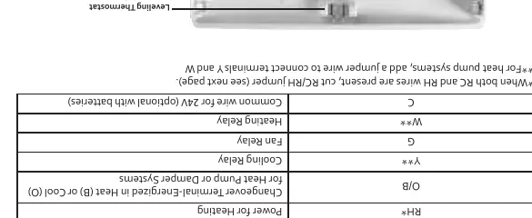
- RC: Power for Cooling
- RH: Power for Heating
- O/B: Changeover terminal for Heat Pump or Damper Systems
- Y: Cooling Relay
- G: Fan Relay
- W: Heating Relay
- C: Common wire for 24V (optional with batteries)
Installer Menu
To access the Installer Menu, hold the Menu button for 8 seconds. Use Next/Back to navigate and arrows to change settings.
- Item 30: Heat Cycle Rate (SLO, MEd, FAS)
- Item 35: Cool Cycle Rate (SLO, MEd, FAS)
- Item 50: Compressor Lockout (On/Off)
- Item 65: Maximum Heat Limit (47 to 99)
- Item 66: Minimum Cool Limit (45 to 97)
- Item 74: Schedule Type (7-day, 5-1-1, or non-programmable)
User Menu
To access the User Menu, hold the Menu button for 0.5 seconds.
- Item 01: Schedule Type
- Item 02: Early Start
- Item 03: Continuous Display Light
- Item 04: Change Air Filter reminder
Programming
The thermostat comes with a factory energy-saving schedule. To modify:
- Set system switch to Heat or Cool.
- Press Menu.
- Press Next to enter schedule.
- Use arrows to set time and temperature for each period (P1-P4).
Troubleshooting
Common issues:
- No Heat/Cool: Check fuse/breaker, ensure system switch is set correctly, check wiring.
- Call for Service icon: System failed to reach setpoint within 2 hours.
- Display blank: Check batteries or reset by removing batteries for 2 minutes.
Practical help
Common problems
No Heat/Cool/Fan
Check fuse or circuit breaker, ensure furnace power switch is ON, check for loose wiring, and ensure the system switch is set correctly.
Call for Service icon appears
The system failed to reach the setpoint within 2 hours. Check system operation.
Display is blank
Check batteries or reset the thermostat by removing batteries for 2 minutes.
Before use
- Verify system power is off at the breaker
- Check wiring against terminal designations
- Install AA batteries if no C-wire is available
- Set Gas/Elec switch correctly for your furnace type
- Level the thermostat on the wall
Specs in practice
- Terminal Load
- 1.0A per terminal, 1.5A maximum for all terminals combined.
- Operating Ambient
- 32°F to +105°F (0°C to +41°C).
- Setpoint Range
- 45°F to 99°F (7°C to 37°C).
Images and diagrams
- Wiring terminal block showing connections for RC, RH, O/B, Y, G, W, and C.
- Installer Menu table listing configuration items 30 through 74.
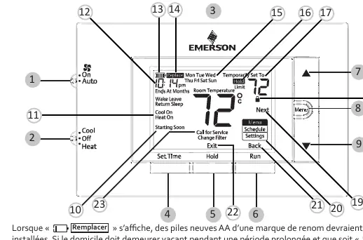
- Thermostat display overview showing icons and button locations.
Model compatibility
- Compatible with gas, oil, electric, and heat pump systems.
- Requires C-wire for continuous backlight operation.
- Not for use on circuits exceeding specified voltage.

Manual page author
Emily Carter
User documentation editor
Prepares concise manual descriptions and highlights the most useful setup, operation, and maintenance information for readers.