HVAC / Thermostats & Controls
User Manual for Emerson 1F75C-11PR Programmable Thermostat
Quick guide for the Emerson 1F75C-11PR programmable thermostat. Includes installation wiring, installer menu settings, programming instructions, and troubleshooting steps.
Quick answers from the manual
Quick answer
- The Emerson 1F75C-11PR is a single-stage programmable thermostat for gas, oil, electric, or heat pump systems. It supports battery or hardwired power and features a 5-1-1 day programmable schedule. p. 1
Key actions
- Access Installer Menu p. 3
- Reset Thermostat p. 8
First start
- Set Time and Day p. 6
Problems and fixes
No Heat/Cool
Check fuse/breaker, furnace switch, and blower door. Verify wiring.
p. 7Maintenance and reset
- Resetting the Thermostat p. 8
Technical specifications
| Parameter | Value | Meaning | Pages |
|---|---|---|---|
| Electrical Rating | mV to 30 VAC | NEC Class II, 50/60 Hz | p. 1 |
| Setpoint Range | 45° to 99° F | 7° to 37° C | p. 1 |
Where to find it in the PDF
- Installation and Wiring p. 2
- Installer Menu p. 3, 4
- Programming p. 6, 7
- Troubleshooting p. 7, 8
Table of contents
Manual images
Click an image to enlargeQuick guide from the manual
The Emerson 1F75C-11PR is a single-stage programmable thermostat compatible with conventional gas, oil, electric (mV and 24V), and heat pump systems (without auxiliary heat). It can be powered by batteries or hardwired with a common (C) wire. This guide covers installation, configuration, and operation.
Installation and Wiring
Before installation, ensure power is disconnected at the main fuse or circuit breaker box. Wiring must conform to local and national electrical codes.
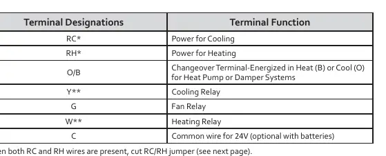
Terminal Designations:
- RC: Power for Cooling
- RH: Power for Heating
- O/B: Changeover terminal for Heat Pump or Damper systems
- Y: Cooling Relay
- G: Fan Relay
- W: Heating Relay
- C: Common wire for 24V (optional with batteries)
Important Notes: If both RC and RH wires are present, cut the RC/RH jumper. For heat pump systems, add a jumper wire to connect terminals Y and W.
Installer Menu
To access the Installer Menu, set the system switch to OFF, then press and hold the temperature up and down buttons simultaneously for 3 seconds.
- 30: Heat Cycle Rate (SLO, MEd, FAS)
- 35: Cool Cycle Rate (SLO, MEd, FAS)
- 50: Compressor Lockout (protects against short cycling)
- 65: Maximum Heat Limit
- 66: Minimum Cool Limit
- 74: Schedule Type (7-Day, 5-1-1 Day, or Non-Programmable)
- 76: Early Start
- 81: Temperature Display Adjustment
- 83: Continuous Display Light
- 86: Change Air Filter Reminder
Programming and Operation
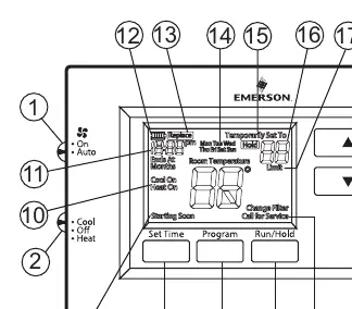
The thermostat defaults to a 5-1-1 day schedule. To set the time and day, press the Set Time button and use the arrow keys. To program the schedule, move the system switch to Heat or Cool, press PRGM, and follow the on-screen prompts to set times and temperatures for the four daily periods (Wake, Leave, Return, Sleep).
Overrides: You can temporarily override the schedule by pressing the arrow keys until the desired temperature is displayed. The thermostat will hold this until the next programmed period.
Troubleshooting
If the thermostat is not functioning correctly, check the following:
- No Heat/Cool/Fan: Check for a blown fuse, tripped circuit breaker, or furnace power switch set to OFF. Ensure the furnace blower door is properly installed.
- Constant Running: Check for shorted wiring.
- "Call for Service" Icon: Indicates the system cannot reach the setpoint within 2 hours or the thermostat needs replacement.
- Resetting: To reset the thermostat, remove batteries for 2 minutes. To reset only the schedule and user settings, press the up, down, and Set Time buttons simultaneously.
Practical help
Common problems
No Heat/Cool/Fan
Check circuit breaker, furnace power switch, and furnace blower door panel. Ensure wiring connections are tight.
Constant running
Check for shorted wiring. If the issue persists, contact an HVAC service person.
"Call for Service" icon displayed
The system failed to reach the setpoint within 2 hours. Check heating/cooling system performance. If "--" is displayed for room temperature, replace the thermostat.
Before use
- Verify system compatibility (Conventional or Heat Pump without Aux).
- Set the Gas/Elec switch correctly (Elec for heat pumps/electric furnaces, Gas for gas/oil).
- Set the O/B terminal switch (O for cooling changeover, B for heating changeover).
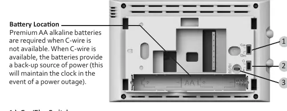
- Install premium AA alkaline batteries if no C-wire is used.
- Ensure wiring matches terminal functions (RC, RH, O/B, Y, G, W, C).
Specs in practice
- Electrical Rating
- mV to 30 VAC, NEC Class II, 50/60 Hz.
- Setpoint Range
- 45° to 99° F (7° to 37° C).
- Terminal Load
- 1.0 A per terminal, 1.5A maximum combined.
Images and diagrams
- Wiring terminal block shows connections for RC, RH, O/B, Y, G, W, C.
- Gas/Elec switch and O/B switch are located on the back of the thermostat.
- Display icons indicate battery status, system mode, and compressor lockout.
Model compatibility
- Compatible with Conventional Gas, Oil, Electric (mV and 24V).
- Compatible with Heat Pump (air source or geothermal) with no Aux. Heat.
- Not compatible with systems requiring auxiliary heat.

Manual page author
David Miller
Documentation analyst
Organizes user manual content into clear summaries, with attention to model details, product context, and everyday usability.