HVAC / Thermostats & Controls
User Manual for Emerson 1F75H-21PR Programmable Thermostat
Quick guide for the Emerson 1F75H-21PR Programmable Thermostat. Includes installation, wiring, programming, installer menu settings, and troubleshooting steps.
Quick answers from the manual
Quick answer
- The Emerson 1F75H-21PR is a programmable heat pump thermostat. It supports battery or hardwired power and features an installer menu for configuring system settings like cycle rates, compressor lockout, and dual fuel logic. p. 1
Key actions
- Access Installer Menu p. 3
- Reset Thermostat p. 8
- Set Time p. 6
First start
- Install batteries or connect hardwire power. p. 2, 3
- Set O/B switch. p. 3
- Configure Installer Menu. p. 3, 4
Problems and fixes
No Heat/Cool
Check fuse, furnace switch, door panel, and wiring connections.
p. 7
Display blank
Reset by removing the batteries for 2 minutes.
p. 8Maintenance and reset
- Reset thermostat settings p. 8
Technical specifications
| Parameter | Value | Meaning | Pages |
|---|---|---|---|
| Electrical Rating | 20 to 30 VAC, NEC Class II, 50/60 Hz | Power requirements | p. 1 |
| Terminal Load | 1.5 A per terminal, 2.5A maximum | Maximum current per terminal | p. 1 |
| Setpoint Range | 45° to 99° F (7° to 37° C) | Temperature control range | p. 1 |
Where to find it in the PDF
- Specifications p. 1
- Installer Menu p. 3, 4
- Troubleshooting p. 7, 8
Table of contents
Manual images
Click an image to enlargeQuick Guide from the Manual
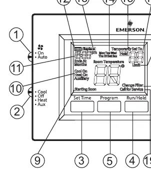
The Emerson 1F75H-21PR is a programmable heat pump thermostat designed for single-stage compressor systems with auxiliary/emergency heat. It can be powered by batteries or hardwired with a common wire. Key operations include setting the time, programming heating/cooling schedules, and accessing the Installer Menu for system configuration.
Installation and Wiring
Precautions: Ensure power is disconnected at the main fuse or circuit breaker before installation. All wiring must conform to local and national electrical codes.
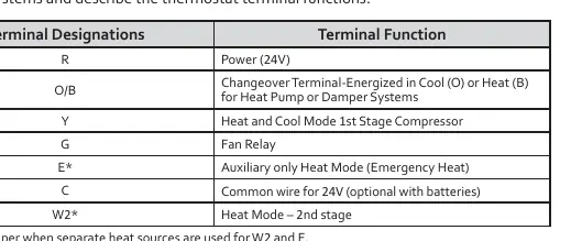
Terminal Designations:
- R: Power (24V)
- O/B: Changeover Terminal (Energized in Cool or Heat)
- Y: Heat and Cool Mode 1st Stage Compressor
- G: Fan Relay
- E: Auxiliary only Heat Mode (Emergency Heat)
- C: Common wire for 24V (optional with batteries)
- W2: Heat Mode – 2nd stage
Note: If your system has separate W2 and E wires, clip the W2/E jumper on the back of the thermostat. The O/B switch is factory set to O; move to B if your system requires B to energize the changeover relay in Heat.
Installer Menu
To access the Installer Menu, set the system switch to OFF, then press and hold the Up and Down buttons for 3 seconds. Use the Up/Down buttons to navigate and change settings.
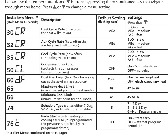
- 30: Heat Cycle Rate (SLO/MEd/FAS)
- 32: Aux Cycle Rate (SLO/MEd/FAS)
- 35: Cool Cycle Rate (SLO/MEd/FAS)
- 50: Compressor Lockout (OFF/On - 5 min delay)
- 60: Duel Fuel Logic (OFF/On)
- 74: Schedule Type (7-Day, 5-1-1 Day, Non-Programmable)
- 76: Early Start (OFF/On)
Operation and Programming
Setting Time: Press the Set Time button, use Up/Down to adjust the hour, press Next for minutes/day, and press Exit when finished.
Programming: The thermostat uses a 5-1-1 day schedule by default. Press PRGM to enter programming mode. Follow the prompts to set times and temperatures for Wake, Leave, Return, and Sleep periods for heating and cooling.
Hold/Override: Press the Hold button for a permanent hold. Press Up/Down to temporarily override the schedule until the next programmed period.
Troubleshooting
If the thermostat is unresponsive or has a blank display, reset it by removing the batteries for 2 minutes. For schedule/user settings reset, hold the Up, Down, and Set Time buttons simultaneously until the display goes blank.
If the "Call for Service" icon appears, check if the heating/cooling system is able to reach the setpoint within 2 hours. If the issue persists, contact a service professional.
Practical help
Common problems
No Heat/Cool/Fan
Check for a blown fuse or tripped circuit breaker. Ensure the furnace power switch is ON and the blower compartment door is properly installed. Tighten all wiring connections.
Display blank or unresponsive
Reset the thermostat by removing the batteries for 2 minutes. If the issue persists, replace the thermostat.
Call for Service icon displayed
Verify the heating/cooling system is functioning. If the system cannot reach the setpoint within 2 hours, contact a service professional.
Before use
- Ensure power is off at the breaker before installation.
- Verify wiring matches terminal designations (R, O/B, Y, G, E, C, W2).
- Install premium AA alkaline batteries if C-wire is not available.
- Set O/B terminal switch correctly for your heat pump (default is O).
- Configure Installer Menu settings for your specific system requirements.
Specs in practice
- Electrical Rating
- 20 to 30 VAC, NEC Class II, 50/60 Hz.
- Terminal Load
- 1.5 A per terminal, 2.5A maximum for all terminals combined.
- Setpoint Range
- 45° to 99° F (7° to 37° C).
- Operating Humidity
- 90% non-condensing maximum.
Images and diagrams
- The wiring terminal block shows R, O/B, Y, G, E, C, W2 connections.
- The leveling mark on the base is for appearance only and does not affect operation.
- Installer Menu navigation uses the Up and Down buttons.
Model compatibility
- Compatible with single stage compressor, heat pump systems (air source or geothermal).
- Supports 1 Stage Aux/Emergency Heat, Electric or Gas (Dual Fuel).

Manual page author
Emily Carter
User documentation editor
Prepares concise manual descriptions and highlights the most useful setup, operation, and maintenance information for readers.