HVAC / Thermostats & Controls
User Manual for Emerson White-Rodgers 1F78 5/2 Day Programmable Thermostat
Comprehensive user manual for the Emerson White-Rodgers 1F78 5/2 Day Programmable Thermostat. Includes installation, wiring diagrams, programming instructions, and troubleshooting.
Quick answers from the manual
Quick answer
- The 1F78 is a 5/2 day programmable thermostat. Installation involves turning off power, labeling wires, mounting the base, and connecting wires according to the specific system diagram provided in the manual. p. 1, 2, 3
Key actions
- Programming 5/2 day schedule p. 5, 6
- Resetting the thermostat p. 6, 7
First start
- Turn off power, remove old thermostat, label wires, mount new base, connect wires, install batteries. p. 1, 2
Problems and fixes
No heat
Check pilot light, system switch, and wiring.
p. 6, 7Maintenance and reset
- Press up arrow, down arrow, and TIME button simultaneously to reset to factory defaults. p. 6, 7
Technical specifications
| Parameter | Value | Meaning | Pages |
|---|---|---|---|
| Electrical Rating | MV to 30 VAC 50/60 Hz or D.C. | Operating voltage range. | p. 6 |
Where to find it in the PDF
- Preparations and Removing Old Thermostat p. 1
- Mounting and Wiring p. 2, 3
- Programming p. 4, 5, 6
- Troubleshooting p. 6, 7
Table of contents
Quick Guide from the Manual
The Emerson White-Rodgers 1F78 is a 5/2 day programmable thermostat designed for heating and cooling systems. Before installation, ensure you have the necessary tools: a flat blade screwdriver, wire cutter/stripper, and a drill with a 3/16 inch bit. Always disconnect electrical power at the main fuse or circuit breaker before starting installation.
Installation and Wiring
Removing the Old Thermostat: Before disconnecting wires, label each wire with its terminal designation. Remove the old thermostat cover and base, ensuring wires do not fall back into the wall.
Mounting the New Base: Remove packing material, pull the cover off the base, and use the base as a template to mark mounting holes. Fasten the base to the wall, ensuring it is level. Push excess wire into the wall and plug the hole with fire-resistant material to prevent drafts.
Wiring: Connect wires beneath terminal screws according to the specific wiring diagram for your system (e.g., heat only, cool only, heat/cool, or heat pump). Ensure the red jumper wire is installed between RH and RC terminals for single-transformer systems.
Operation and Features
The thermostat features a 5/2 day programming schedule, allowing you to set different programs for weekdays and weekends. It includes Energy Management Recovery (EMR), which starts the system early to reach the setpoint at the programmed time. You can disable EMR by clipping jumper W903.
Battery Operation: The unit requires 2 AAA alkaline batteries. When the low battery indicator appears, replace them immediately to ensure continued operation.
Programming
To program the thermostat:
- Set Time and Day: Press the TIME button and use the arrow keys to set the current time and day.
- Heating/Cooling Program: Press PRGM to enter the programming mode. Select the weekday or weekend program and set the start times and temperatures for each of the four periods.
- Review: Use the PRGM button to cycle through and verify your programmed settings.
Troubleshooting
If the thermostat is not functioning correctly, try the following:
- Reset: Press the up arrow, down arrow, and TIME button simultaneously to reset to factory defaults.
- No Heat/Cool: Check if the system switch is set correctly, ensure wiring is secure, and verify that the pilot light is lit (if applicable).
- Display Issues: If the display is blank, replace the batteries.
Practical help
Common problems
No heat
Check if the pilot light is lit, the system switch is set to HEAT, and all wiring connections are secure.
No cool
Ensure the system switch is set to COOL, check wiring, and wait up to 5 minutes for the compressor delay to finish.
Display blank or keypad not responding
Replace the batteries or perform a reset by pressing the up arrow, down arrow, and TIME button simultaneously.
Before use
- Turn off power at the main fuse or circuit breaker.
- Label all wires before disconnecting the old thermostat.
- Ensure you have a flat blade screwdriver, wire cutter/stripper, and a drill.
- Verify system compatibility using the chart in the manual.
- Install 2 fresh AAA alkaline batteries.
Specs in practice
- Electrical Rating
- MV to 30 VAC 50/60 Hz or D.C.; 0.05 to 1.0 Amps per terminal; 1.5 Amps max total load.
- Setpoint Temperature Range
- 45°F to 90°F (7°C to 32°C).
- Operating Humidity
- 0 to 90% RH (non-condensing).
Images and diagrams
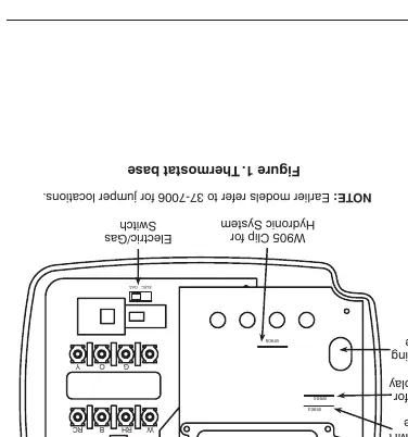
- Figure 1: Shows the thermostat base, mounting holes, and jumper locations (W903, W904, W905).
- Wiring Diagrams (Figures 2-7): Provide specific connection instructions for various system types including heat only, cool only, heat/cool, and heat pump.
Model compatibility
- Compatible with most 24V systems.
- Not compatible with line voltage (110/240V) systems.
- Not compatible with multistage systems.
- Not compatible with systems exceeding 30VAC/1.5A.

Manual page author
Michael Turner
Technical manual editor
Reviews PDF manuals for structure, safety notes, and practical product details so readers can find the right information quickly.