Electronics / Video Transmission
User Manual for Extron MTP T 15HD A Architectural Twisted Pair Transmitters
Quick guide for the Extron MTP T 15HD A Architectural Twisted Pair Transmitters. Includes installation steps for wall boxes and AAP, wiring diagrams for power and RJ-45, and EDID configuration settings.
Table of contents
Manual images
Click an image to enlargeQuick guide from the manual
The Extron MTP T 15HD A series consists of wall-mounted transmitters designed for long-distance distribution of high-resolution video and audio over twisted pair cable. This guide covers the installation, connection, and configuration of the WM, D, and AAP models.
Installation
The MTP T 15HD A transmitters can be installed in standard one-gang electrical wall boxes or furniture. Ensure the wall box is at least 2.5 inches (6.4 cm) deep to accommodate connectors and cables.
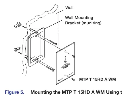
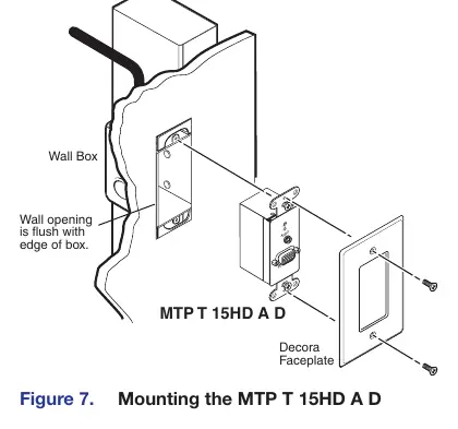
Installing the MTP T 15HD A WM and MTP T 15HD A D
- Prepare the site by marking the template dimensions on the wall or furniture.
- Cut out the material and insert the wall box or mud ring.
- Feed output cables through the opening and secure them with cable clamps.
- Trim and insulate exposed cable shields to prevent short circuits.
- Connect output device cables to the rear of the wall plate.
- Connect input devices to the front panel, restore power, and test the installation.
Installing the MTP T 15HD A AAP
- Insert the standoffs of the AAP through the holes in the device faceplate or AAP wall plate.
- Secure the AAP to the faceplate using the provided #4-40 nuts and captive washers.
- Cover any remaining openings in the faceplate with blank plates.
- Perform an installation pretest before final mounting.
Connections and Settings
Front Panel Features
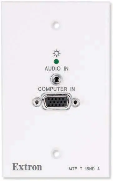
- Power LED: Indicates that power is applied to the unit.
- Audio Input Connector: 3.5 mm stereo jack for unbalanced audio input.
- Video Input Connector: 15-pin HD connector for high-resolution video input.
Rear Panel Features
- Output Connector: RJ-45 female connector for twisted pair cable.
- Pre-Peak Switch: Boosts video signal output to correct for long cable runs. Refer to the transmission distance table in the manual for settings.
- Stereo Audio Output Connector: 5-pole captive screw connector for audio output.
- EDID Select Rotary Switch: Used to select factory-installed EDID information.
- Frequency Select Switch: Sets the vertical frequency (50 Hz or 60 Hz) for the EDID.
Power Supply Wiring and Grounding
The unit requires an external 12 VDC power supply. Ensure correct polarity; the negative lead is identified by ridges on the side of the cord. The ideal length for exposed copper wires is 3/16 inches (5 mm). Use the supplied tie wrap to secure the power cord to the connector.
Twisted Pair Cable Termination
Termination must comply with TIA/EIA T568A or T568B wiring standards. Ensure the same standard is used on both ends of the cable. Extron Enhanced Skew-Free AV UTP cable is recommended for best performance.
EDID Minder Configuration
To use factory-installed EDID information:
- Connect the source device to the transmitter.
- Set the rear panel Frequency Select DIP switch to 50 Hz or 60 Hz.
- Set the EDID Select rotary switch to the required position (1-F) corresponding to the desired resolution.
Manufacturer information
Extron Electronics
Practical help
Common problems
Poor image quality over long cable runs
Adjust the Pre-Peak switch on the rear panel based on the cable length and video resolution.
Power supply issues
Verify 12 VDC power supply polarity; incorrect polarity can damage the unit. Identify the negative lead by the ridges on the cord.
Audio issues with unbalanced connections
Connect the sleeves to the ground contact, not the negative (-) contact.
Before use
- Ensure the wall box is at least 2.5 inches (6.4 cm) deep.
- Verify the twisted pair cable is terminated according to TIA/EIA T568A or T568B standards.
- Check that the power supply is 12 VDC, max 1.0 A, and marked Class 2 or LPS.
- Test the cable run before final installation.
- Ensure the Pre-Peak switch is set correctly for the cable length.
Specs in practice
- Pre-Peak Switch
- Boosts video signal output to compensate for signal loss over long cable runs.
- Frequency Select
- Sets the vertical frequency (50 Hz or 60 Hz) for the EDID.
Images and diagrams
- Figure 5: Mounting the MTP T 15HD A WM using a mud ring.
- Figure 11: Captive screw audio connector wiring for balanced and unbalanced audio.
- Figure 14: Twisted pair cable termination diagram for RJ-45 connectors.
Model compatibility
- Compatible with Extron Enhanced Skew-Free AV UTP cable, or CAT 5, 5e, or 6 STP/UTP/FTP cable.
- Not recommended for Ethernet or LAN applications.
- Audio data on wire pairs 3 and 6 is incompatible with Extron TPX 88 A.

Manual page author
Michael Turner
Technical manual editor
Reviews PDF manuals for structure, safety notes, and practical product details so readers can find the right information quickly.