Electronics / Video Transmission
User Manual for SIIG HDMI Over IP Extender 150m
Comprehensive user guide for the SIIG HDMI Over IP Extender (150m). Includes installation steps, wiring diagrams for one-to-one and one-to-many setups, IR extension instructions, and troubleshooting tips.
Table of contents
Manual images
Click an image to enlargeQuick Guide from the Manual
The SIIG HDMI Over IP Extender allows you to extend high-definition 1080p HDMI signals over a single Cat5e/6 cable up to 150 meters (492ft). It supports direct one-to-one connections or one-to-many configurations over IP networks. For optimal performance, use 100% copper 23AWG Cat5e/6 cables and dedicated Gigabit Ethernet switches with IGMP support.
Package Contents
- 1x HDMI Over IP Extender (TX+RX)
- 2x Power Adapters (DC 5V/1A)
- 2x IR Blaster and Receiver cables
- 1x User Manual
Device Layout
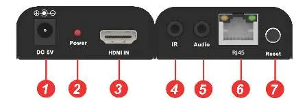
Transmitter (TX)
The transmitter features a DC 5V power input, Power LED, HDMI IN port, IR port, Audio output, RJ45 network port, and a Reset button (press for 5 seconds to reset the video signal).
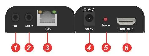
Receiver (RX)
The receiver features an IR port, Audio output, RJ45 network port, DC 5V power input, Power LED, and an HDMI OUT port.
Hardware Installation
- Power off all devices, including the HDMI source and display.
- Connect the HDMI source to the Transmitter's HDMI IN port using an HDMI cable.
- Connect the IR Blaster cable to the Transmitter's IR port and position the eye towards the source device's IR sensor.
- Connect a Cat5e/6 cable between the Transmitter and Receiver RJ45 ports.
- Connect the HDMI display to the Receiver's HDMI OUT port.
- Connect the IR Receiver cable to the Receiver's IR port.
- Connect the included 5V power adapters to both the Transmitter and Receiver.
- Power on the HDMI source and display.
Wiring Standards
For best performance and compatibility, both RJ45 connectors must be wired identically using the T568B standard. Avoid using CCA (Copper Clad Aluminum) cables; 100% copper 23AWG is recommended.
Application Diagrams
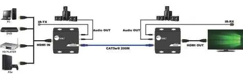
One to One Mode
Direct connection between the Transmitter and Receiver or through a Gigabit LAN via a dedicated gigabit switch hub.
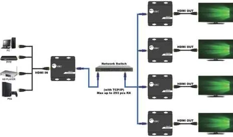
One to Many Mode
Requires a dedicated Gigabit switch. If using an existing network, configure a VLAN to segregate the Transmitter and Receivers from other network traffic. Each VLAN can support only one Transmitter, but up to 253 Receivers.
Troubleshooting
- Display shows 'Please check the TX and RX connection': Verify power adapters are connected and the network cable is firmly plugged in.
- Display shows 'X' on Transmitter: Ensure the HDMI source is connected and powered on; try a different HDMI cable.
- Display shows 'X' between Transmitter & Receiver: Check the network cable connection and reseat the receiver's power adapter.
- General issues: Ensure HDMI cables are under 5m and network cables are under 150m. Press the reset button on the transmitter for 5 seconds.
Specifications
- HDMI Signal: HDMI 1.3 and HDCP 1.2 compatible
- Resolution: Up to 1080p@60Hz
- Transmission Distance: Up to 150m (492ft)
- Power: 5V DC / 1A (4W consumption per unit)
- Operating Temperature: 5° to 131° F (-15° to 55° C)
Manufacturer information
SIIG, Inc.
Practical help
Common problems
Display shows 'Please check the TX and RX connection'
Check if power adapters for both units are connected and powered on. Ensure the network cable (Cat5e/6) is firmly connected.
Display shows 'X' on the Transmitter
Ensure the HDMI source device is connected to the Transmitter and powered on. Try using a different HDMI cable.
Display shows 'X' between Transmitter & Receiver
Check that the network cable is tight and reseat the receiver's power adapter.
Extender not working properly
Verify cable lengths (HDMI max 5m, Network max 150m) and press the reset button on the transmitter for 5 seconds.
Before use
- Power off all devices before installation.
- Use 100% copper 23AWG Cat5e/6 cables.
- Ensure you have the included 5V power adapters.
- If using a network switch, ensure it is a Gigabit switch with IGMP support.
- Configure a dedicated VLAN if connecting to an existing network.
Specs in practice
- Transmission Distance
- Maximum range is 150m (492ft) over a single Cat5e/6 cable.
- Power Consumption
- 4W for both Transmitter and Receiver units.
- Operating Temperature
- Device operates between 5° to 131° F (-15° to 55° C).
Images and diagrams
- Transmitter Layout: Identifies ports for DC 5V, HDMI IN, IR, Audio, RJ45, and the Reset button.
- Receiver Layout: Identifies ports for IR, Audio, RJ45, DC 5V, and HDMI OUT.
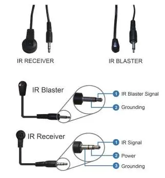
- IR Pin Definition: Shows the wiring configuration for IR Blaster and IR Receiver cables.
Model compatibility
- Requires Gigabit Ethernet switch for one-to-many setups.
- Supports up to 253 Receivers in one-to-many mode.
- HDMI 1.3 and HDCP 1.2 compatible.

Manual page author
Michael Turner
Technical manual editor
Reviews PDF manuals for structure, safety notes, and practical product details so readers can find the right information quickly.