Electronics / Monitors
User Manual for Fanatec CSL Pedals Load Cell Kit
Comprehensive user guide for the Fanatec CSL Pedals Load Cell Kit. Includes assembly instructions, connection steps, tuning options, and troubleshooting tips for optimal performance.
Table of contents
Manual images
Jump to the sectionQuick guide from the manual
The Fanatec CSL Pedals Load Cell Kit is a high-performance upgrade for your pedal set. Before starting, ensure you have updated your wheel base and pedal firmware using the latest PC driver from Fanatec.com/driver. Important: Do not connect the pedals via RJ12 and USB at the same time. Always place the box on its side when removing contents to avoid damage.

Package Contents
- 1x CSL Pedals Load Cell Module
- 1x USB Cable (~180 cm)
- 1x RJ12 Cable (~45 cm)
- 4x Countersunk Torx Bolts
- 1x T20 Torx Key
Assembly
Follow these steps to attach the Load Cell module to your existing CSL Pedals set:
- Remove the RJ12 cable of the standard brake module from the accelerator pedal module and remove it from the cable management clips.
- Remove the bolts of the brake and accelerator pedal units from the heel rest.
- Move the brake and accelerator pedal modules outwards to create space.
- Place the CSL Pedals Load Cell Kit module under the heel rest in your preferred position.
- Insert the included bolts and firmly secure the pedal units to the heel rest using the T20 Torx key.
Pedal Plate Adjustment
The pedal plate is height-adjustable. There are 3 height settings that can be adjusted in descending increments of 15 mm. Use the included T20 Torx key to loosen the bolts and adjust the plate to your preference.
Connections
Depending on your setup, connect the Load Cell module as follows:
- Option 1 (PC): Connect the CSL Pedals Load Cell module directly to a Windows PC via the included USB cable.
- Option 2 (Wheel Base): Connect the module to a Fanatec wheel base via the RJ12 cable.
Ensure the RJ12 cable is connected to the 'Wheel Base / Load Cell' port of the accelerator module and the 'Load Cell' port of the Load Cell module.
Tuning Options
After installing the Fanatec PC Driver, open the Fanatec Control Panel to access tuning settings:
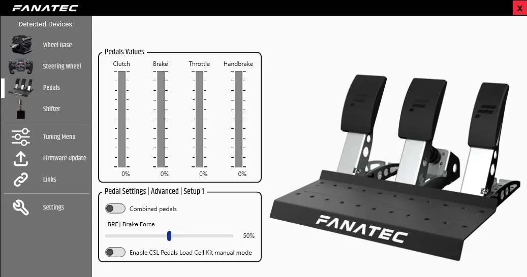
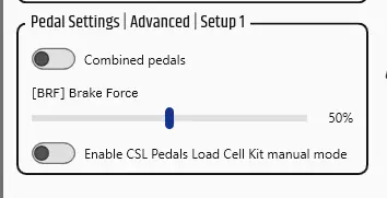
- BRF (Brake Force): Adjusts the pressure required to reach 100% brake input. 'Lo' requires the least pressure, while higher values require more.
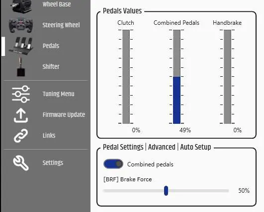
- Combined Pedals: Allows the brake and accelerator to operate on a single axis, useful for older games.
- Manual Mode: Enables manual setting of minimum and maximum values for each pedal throughout their mechanical travel range.
Cleaning and Maintenance
Clean the device only with a dry or slightly damp microfibre cloth. Do not use cleaning solutions as they may damage the unit. Do not open the casing, as this will void the warranty.
Troubleshooting
If the device is not recognized, ensure you are using the correct RJ12 cable and that it is plugged into the correct ports. If pedal signals feel incorrect, perform a manual calibration in the Fanatec Control Panel or reselect 'Manual Mode'. If your PC does not boot with the pedals connected via USB, boot the PC first and then connect the device.
Official resources from the manual
Manufacturer information
Fanatec
Practical help
Common problems
PC driver or wheel base does not recognize the Load Cell Kit.
Ensure firmware is updated via the latest PC driver, use the included RJ12 cable, and verify all cables are plugged into the correct ports.
Manually calibrated pedal positions are reset.
After a firmware update, you must perform the manual calibration again via the 'Tuning Options' menu.
Pedal signal behavior feels incorrect.
Check indicator bars in the Fanatec Control Panel and perform a manual calibration of minimum/maximum positions.
PC does not boot when pedals are connected via USB.
Boot the PC first, then connect the CSL Pedals Load Cell Kit via USB.
Before use
- Update wheel base and pedal firmware using the latest PC driver.
- Ensure you are using the included RJ12 cable.
- Do not connect the pedals via RJ12 and USB at the same time.
- Place the box on its side when removing contents to avoid damage.
- Verify all connections are secure before powering on.
Specs in practice
- BRF (Brake Force)
- Adjusts the force required to reach 100% brake input. Range: Lo to 100.
- Combined Pedals
- Allows brake and accelerator to operate on a single axis for compatibility with older games.
Images and diagrams
- The manual provides diagrams for the assembly sequence, showing how to move pedal modules and secure them to the heel rest.
- Connection diagrams illustrate the correct ports for RJ12 cables between the accelerator, load cell, and wheel base.
- The Fanatec Control Panel screenshots show where to adjust BRF, Combined Pedals, and Manual Mode settings.
Model compatibility
- Compatible with all CSL, CSL Elite, ClubSport, and Podium series wheel bases.
- Can be used standalone on a PC when attached to a CSL Pedals set.
- Windows PC is required for firmware updates.

Manual page author
David Miller
Documentation analyst
Organizes user manual content into clear summaries, with attention to model details, product context, and everyday usability.