Documents / Warranty Safety
Installation and Usage Manual for Fiamma F45eagle Awning
Comprehensive installation and usage guide for the Fiamma F45eagle awning. Includes wiring diagrams, Sismic Sensor setup, inclination adjustment, and maintenance instructions.
Table of contents
Manual images
Jump to the sectionQuick guide from the manual
The Fiamma F45eagle is a self-supporting awning designed for vehicle installation. This manual covers the installation of the adapter, mounting the awning, electrical connections, and the operation of the automatic Sismic Sensor. Always ensure the vehicle wall is solid enough to support the awning before installation. The awning operates on 12V DC and requires a 12A fuse for the main power line.
Installation and Mounting
The installation process involves several critical steps:
- Mounting the adapter: Ensure the adapter is mounted linearly without curves or deformations. Use shims if necessary to ensure the bracket is perfectly aligned with the vehicle wall.
- Mounting the awning: Secure the awning onto the adapter brackets.
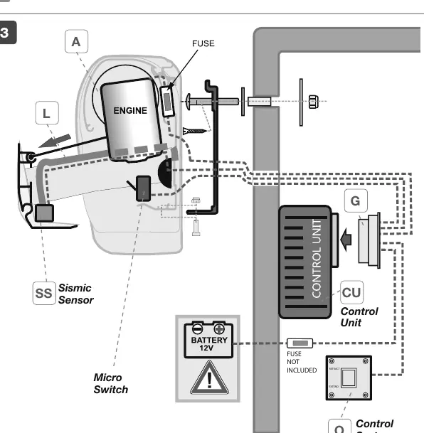
- Electrical connection: Connect the Control Unit (CU) inside the vehicle near the motor. The system must be powered by a 12V line protected by a 12A fuse.
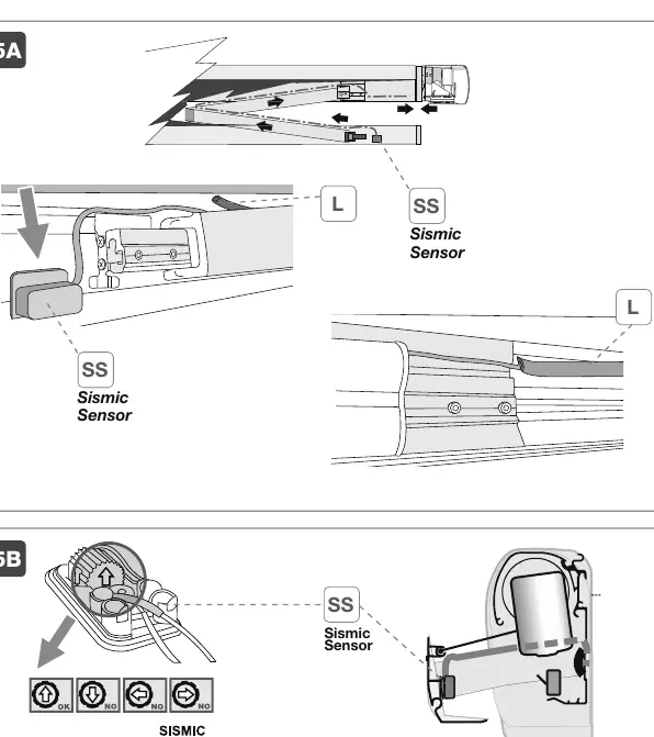
- Sismic Sensor (SS): Install the sensor inside the lead bar. Route the wire along the arm, secure it with sheath L, and connect it to the control unit.
Electrical System and Wiring
The system includes a Control Unit, a Sismic Sensor, and a Micro Switch. The motor is protected by a 5x20 T 6,3A L 250V fuse. Never operate the product without a fuse. The wiring diagram (page 11 and 21) details the connections between the motor, control unit, battery, and the Sismic Sensor.
Operation
The F45eagle features both standard and automatic operation:
- Standard Operation: Use the control system button to open or close the awning. Movement stops when the button is released.
- Automatic Operation: The Sismic Sensor detects oscillatory movements (e.g., strong wind) and automatically closes the awning. Do not interrupt this cycle.
- Sensitivity Adjustment: The Sismic Sensor sensitivity can be adjusted via a potentiometer. The factory setting is 5. Setting it to 0 disables the sensor.
- Manual Operation: In case of motor failure, use the provided crank handle D to manually close the awning.
Inclination Adjustment
The inclination of the awning can be adjusted to suit your needs:
- Lightly loosen screw A.
- Completely unscrew the stop screw C.
- Operate on screw B: clockwise raises the arm (decreases inclination), counter-clockwise lowers the arm (increases inclination).
- Check the degrees indicator D to ensure both arms are aligned.
- Inside the lead bar, unscrew the two screws T and rotate the stop plate to the desired degree position.
Maintenance
To ensure longevity, follow these maintenance guidelines:
- Cleaning: Only close the awning when it is dry and clean. If you must close it while wet, open it within 12 hours to dry.
- Fabric Care: Use clean water and a cloth or brush for cleaning. For stubborn dirt, use a neutral detergent (Marseille soap). Do not use aggressive chemicals or high-pressure cleaners.
- Temperature: Do not use the awning at temperatures below 0°C.
Manufacturer information
Fiamma SpA
Practical help
Common problems
Awning does not open or close
Check the 12V power supply, the 12A main fuse, and the motor fuse (5x20 T 6,3A L 250V).
Sismic Sensor not responding to wind
Check the sensitivity setting on the potentiometer (factory default is 5). Ensure the sensor is not set to 0 (disabled).
Awning stops unexpectedly during automatic closing
Ensure there are no obstacles in the path of the lead bar. The Micro Switch must be activated to stop the motor.
Before use
- Ensure the vehicle wall is solid enough to support the awning.
- Verify the 12V power supply is connected correctly.
- Check that the awning is completely dry before closing.
- Ensure no obstacles are in the path of the awning.
- Verify the Sismic Sensor sensitivity is set correctly.
Specs in practice
- Power Supply
- 12V DC
- Motor Protection Fuse
- T 6,3A L 250V
- General Protection Fuse
- 12A
- Operating Temperature
- +5°C to +50°C
Images and diagrams
- Wiring diagram shows connections for Control Unit, Sismic Sensor, Micro Switch, and 12V battery.
- Inclination adjustment diagram shows screws A, B, C, and T for setting the angle.
Model compatibility
- Requires 12V power supply.
- Must be installed on a solid vehicle wall.
- Not for use in temperatures below 0°C.

Manual page author
Michael Turner
Technical manual editor
Reviews PDF manuals for structure, safety notes, and practical product details so readers can find the right information quickly.