Music / Vocal Effects
User Manual for Flamma FV04 Vocal Harmony Pedal
Quick guide for the Flamma FV04 Vocal Harmony Pedal. Learn how to set harmony modes, adjust reverb, configure output modes, and use the footswitch controls.
Table of contents
Quick guide from the manual
The Flamma FV04 is a vocal harmony pedal designed for vocalists, featuring 12 pitches with 11 harmony modes, dedicated reverb effects, and support for guitar input. This guide provides essential instructions for setup, operation, and configuration.
Top Panel Controls
The top panel contains the primary controls for the pedal:
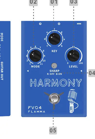
- MODE: Selects between 11 different harmony modes.
- KEY: Selects the scale root note.
- LEVEL: Controls harmony volume or guitar reverb volume.
- SHARP LED button: Used for semitone/vocal tone mode selection.
- FOOTSWITCH: Powers the pedal on/off and accesses hidden modes.
Setup and Connections
Ensure you use a power adapter supplying DC 9V 1.5A, center negative. Connect your microphone to the MIC IN jack and your guitar to the GUITAR IN jack. Use the XLR OUT for balanced output to your mixer or PA system. Use the LIFT/GND switch to manage ground loops.
Harmony and Scale Selection
To achieve accurate harmony, select the correct root note using the KEY knob. Press the SHARP button to modulate to higher semitones. To select a minor scale, press the SHARP button twice quickly; the button will blink. Press it twice again to toggle back to the major scale.
Reverb and Vocal Tone
The FV04 features individual reverb effects for vocal and guitar:
- Vocal Reverb: Press and hold the SHARP button while rotating the LEVEL knob to adjust the vocal reverb level.
- Guitar Reverb: Press and hold the footswitch to enter hidden mode (LED turns yellow), then rotate the LEVEL knob to adjust the guitar reverb.
- Vocal Tone Mode: While in hidden mode, press the SHARP button to cycle through Normal (LED off), Warm (Red LED), and Bright (Blue LED) tones.
Footswitch Modes
The footswitch controls the activation of effects:
- On/Off: Press to turn on both harmony and reverb. Press twice quickly to turn off.
- Harmony Toggle: Press once while on to toggle harmony effect on/off (Red LED = off, Green LED = on).
- Hidden Mode: Press and hold to enter hidden mode (LED turns yellow).
Output Modes
To switch between output modes, press and hold the footswitch while powering on the device. The TONE button and footswitch LED will indicate the mode:
- Individual Mode (Blue): Guitar signal goes to GUITAR OUT; microphone signal goes to XLR OUT.
- Mixed Mode (Red): Both guitar and microphone signals go through both outputs.
Specifications
- Guitar In: 1/4 inch mono jack (1 Mohms impedance).
- Guitar Out: 1/4 inch mono jack (100 ohms impedance).
- Mic In: XLR balanced (2.14k ohms impedance).
- XLR Output: XLR balanced (300 ohms impedance).
- Power Requirements: DC 9V 1.5A.
- Frequency Response: 20Hz-20KHz.
Practical help
Common problems
No sound output
Check that the power adapter is 9V DC 1.5A and properly connected. Verify cable connections to MIC IN/GUITAR IN and outputs.
Harmony sounds incorrect
Ensure the correct Key/Root note is selected using the KEY knob and that the correct scale (Major/Minor) is set.
Reverb level cannot be adjusted
Ensure you are holding the SHARP button while rotating the LEVEL knob for vocal reverb, or holding the footswitch to enter hidden mode for guitar reverb.
Before use
- Connect a 9V DC 1.5A center-negative power adapter.
- Connect microphone to MIC IN.
- Connect guitar to GUITAR IN.
- Set the desired Key/Root note.
- Configure the output mode (Individual or Mixed) before starting.
- Ensure the LIFT/GND switch is set correctly to avoid hum.
Specs in practice
- 48V Phantom Power
- Required for condenser microphones; can be toggled on the rear panel.
- Individual Output Mode
- Separates guitar and vocal signals to different outputs.
- Mixed Output Mode
- Combines both guitar and vocal signals into both outputs.
Images and diagrams
- The top panel diagram illustrates the placement of the Mode, Key, and Level knobs, the Sharp button, and the footswitch.
- The rear panel diagram shows the location of the Line In, Mic In, XLR Out, Gain, Lift/GND, and DC In ports.
Model compatibility
- Supports 48V phantom power for condenser microphones.
- Line-In mode allows connection of other FV series pedals to the MIC IN jack.

Manual page author
Michael Turner
Technical manual editor
Reviews PDF manuals for structure, safety notes, and practical product details so readers can find the right information quickly.