Power / Solar Inverters
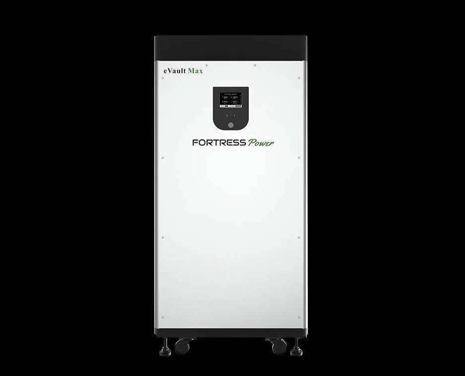
Installation Manual for Fortress Power eVault Max 18.5kWh Battery
Comprehensive installation and operation guide for the Fortress Power eVault Max 18.5kWh LFP battery. Includes safety precautions, wiring diagrams, parallel configuration steps, and troubleshooting.
Quick answers from the manual
Quick answer
- The Fortress Power eVault Max 18.5kWh is a Lithium Ferro Phosphate battery. Installation requires qualified personnel. Key steps include mechanical mounting, connecting DC cables (observing polarity), grounding, and configuring communication for parallel setups. p. 3, 10, 12
Key actions
- Commissioning a single unit p. 12
- Parallel configuration p. 15, 16
First start
- Push power button for 8 seconds until status light and LCD light up. p. 12
Problems and fixes
ALARM LED on
Check for HV, LV, HT, LT, OC, or SC conditions. Use BMS Tool to diagnose.
p. 17, 21Maintenance and reset
- Reset BMS by pushing the POWER Button for at least 10s. p. 20
Technical specifications
| Parameter | Value | Meaning | Pages |
|---|---|---|---|
| Total Energy | 18.5 kWh | Capacity | p. 8 |
| Voltage | 51.2V | p. 8 |
Where to find it in the PDF
- Installation p. 9, 10, 11, 12
- Parallel Configuration p. 13, 15, 16
- Troubleshooting p. 21, 22, 23, 24
Table of contents
Manual images
Click an image to enlargeQuick Guide from the Manual
The Fortress Power eVault Max 18.5kWh is a Lithium Ferro Phosphate (LFP) battery system. Installation must be performed by qualified personnel. Key steps include mechanical mounting, connecting DC cables (observing polarity), grounding, and configuring communication for parallel setups. Always verify polarity with a voltmeter before energizing.
Safety Precautions
- Risks of Fire/Explosion: Do not expose to temperatures above 122°F (50°C), do not crush, puncture, or subject to strong impacts.
- Electric Shock: Do not disassemble the battery. Do not touch with wet hands.
- Installation: Disconnect utility grid and solar input before wiring. Use insulated tools and PPE.
- Compatibility: Do not combine with other brands or chemistries.
Installation
Mechanical Installation
The unit is designed to stand on the floor using adjustable support legs. For high seismic areas, use the wall bracket. Ensure the floor is flat and level (inclination < 15°).
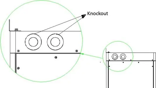
Electrical Connections
Terminals are located under the top cover. Use heavy-duty 3/8" (10mm) ring terminals. Recommended torque is 10.0–19.1 Nm. Ensure the battery DC breaker is OFF during connection. Always verify polarity before energizing.
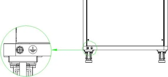
Grounding
The unit features two grounding lugs on the bottom of the battery case. Use at least 6AWG (16mm²) copper wire.
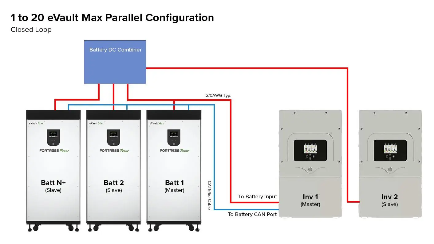
Parallel Configuration
Up to 20 units can be connected in parallel. Maintain identical wire lengths and types from each battery to the DC combiner. Connect the COM_Parallel OUT port of one unit to the IN port of the next using CAT5/5e cables. Set the communication matching resistor to 120Ω on the first and last batteries in the chain; set others to OFF.
Operating
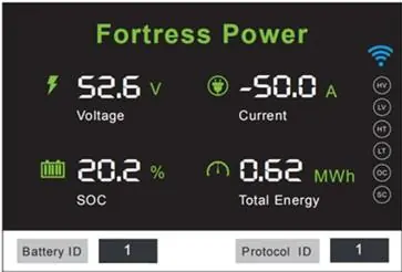
The battery features a built-in Battery Management System (BMS). The LCD provides voltage, current, SOC, and power output. When charging, current is negative; when discharging, it is positive. Ensure the inverter/charger is programmed according to manufacturer recommendations for LFP batteries.
Troubleshooting
If the ALARM LED is on, check for High Voltage (HV), Low Voltage (LV), High/Low Temperature (HT/LT), Open Circuit (OC), or Short Circuit (SC) conditions. Use the BMS Tool software on a Windows computer for detailed diagnostics if the problem persists.
Practical help
Common problems
ALARM LED is on but unit functions
Check inverter settings and use the BMS Tool software to diagnose the specific alarm condition.
Unit voltage is extremely low or bleeding down
BMS is in Protection Mode. Use a 48V charger to trickle charge the battery or use the BMS-to-Computer Adapter Cable to reset relays.
LCD Display went dark
The display turns off after 60 seconds of inactivity to save energy. If it does not wake up, check internal connections.
Battery ID conflict
Ensure Battery ID is set to 0 for a single unit, or 1-N for parallel configurations.
Before use
- Check battery package for damage and completeness
- Verify terminals are clean and free of corrosion
- Ensure all cables are tight and not frayed
- Check torque on terminal bolts
- Verify polarity with a voltmeter before energizing the system
Specs in practice
- Total Energy
- 18.5 kWh capacity
- Max Charge/Discharge Current
- 180A continuous
- Enclosure Rating
- IP55 (indoor use only)
Images and diagrams
- Parallel configuration wiring diagram showing master/slave setup
- Communication port pinouts for Inverter and Parallel connections
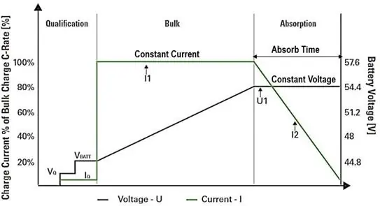
- Charging stage curve (Bulk/Absorption)
Model compatibility
- Compatible with most 48V Inverter/Chargers
- Do not mix with other brands or chemistries
- Parallel operation only; do not arrange in series

Manual page author
Michael Turner
Technical manual editor
Reviews PDF manuals for structure, safety notes, and practical product details so readers can find the right information quickly.