Toys / RC Components
User Manual for Futaba 32MZ-WC Digital Proportional R/C System
Comprehensive user guide for the Futaba 32MZ-WC transmitter. Includes setup, antenna handling, battery charging, link procedures, and safety precautions.
Quick answers from the manual
Quick answer
- The Futaba 32MZ-WC is a 26-channel digital proportional R/C system. It features a color touch screen, FASSTest technology, and supports S.BUS2 sensors. p. 10, 40
Key actions
- Linking a receiver p. 33
- Charging the battery p. 22
First start
- Ensure battery is connected, throttle is at idle, and perform a range test. p. 7, 8, 30
Problems and fixes
Screen freezes
Remove and reinsert the battery to force a cold restart.
p. 30Maintenance and reset
- Resetting the system timer p. 31
Technical specifications
| Parameter | Value | Meaning | Pages |
|---|---|---|---|
| Frequency | 2.4 GHz | Operating frequency band | p. 40 |
| Battery | 3.8V Li-polymer | Power supply | p. 40 |
Where to find it in the PDF
- Transmitter Overview p. 11
- Link Procedure p. 33
Table of contents
Manual images
Click an image to enlargeQuick Guide from the Manual
The Futaba 32MZ-WC is a high-performance 26-channel digital proportional R/C system. Before operation, ensure the battery is fully charged and the transmitter is initialized. Always turn on the transmitter first, then the receiver. When turning off, turn off the receiver first, then the transmitter.
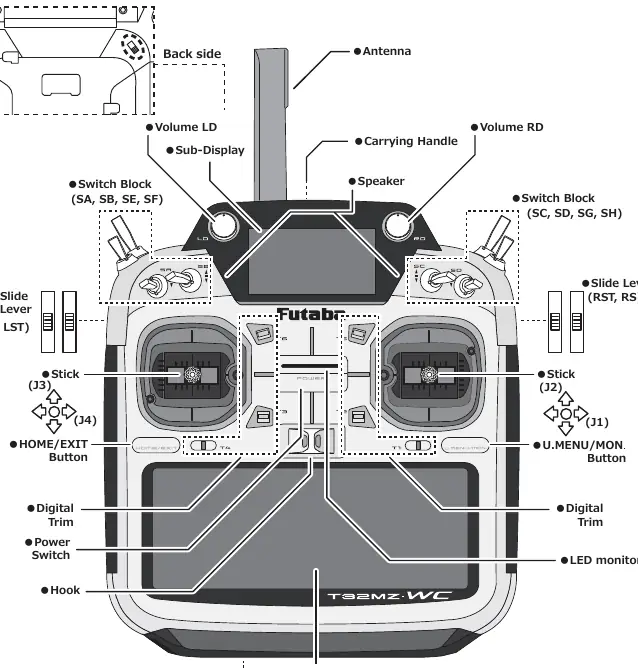
Transmitter Overview
The transmitter features a color LCD touch screen, dual ball-bearing sticks with magnetic detection, and replaceable toggle switches. The antenna is adjustable for optimal signal strength. The system runs on Windows Embedded Compact 7.
Setup and Adjustments
- Stick Tension: Adjustable for airplane or helicopter preferences. Use the 1.5mm hexagonal wrench to adjust tension screws.
- Stick Length: Adjustable by rotating the lever head.
- Battery Exchange: Slide the battery cover to access the battery. Ensure the connector is secure.
- Battery Charging: Use only the included AC adapter. Connect to the CHG port with the transmitter powered OFF.
- microSD Card: Used for storing model data, music, and voice files. Insert into the slot on the bottom of the transmitter.
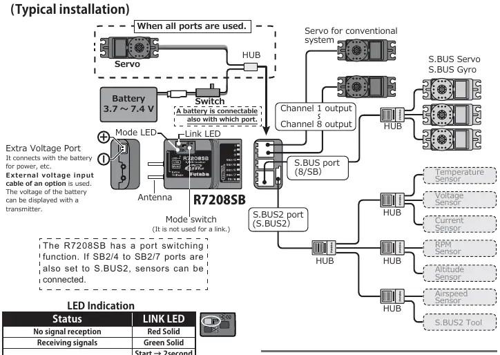
Receiver and Linking
The system supports FASSTest, FASST, S-FHSS, and T-FHSS protocols. Linking is required for each new model or when changing system types.
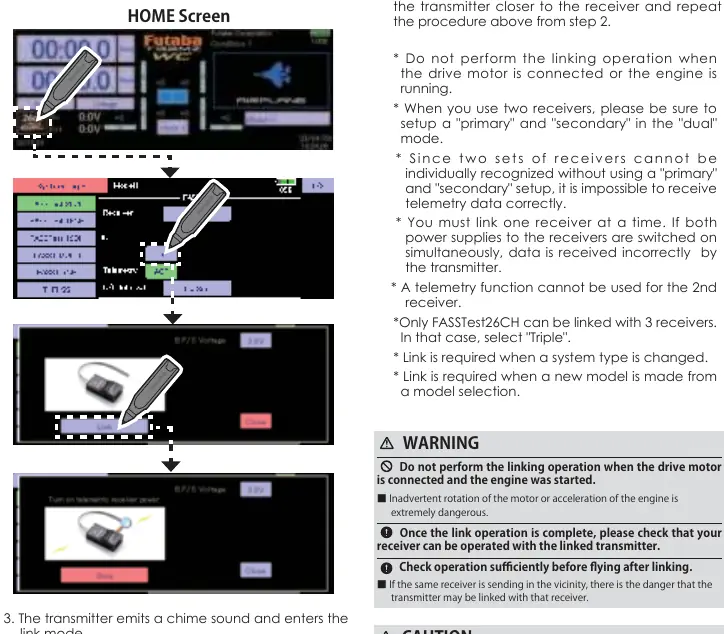
Link Procedure
- Bring the receiver within 50 cm of the transmitter.
- Set the transmitter to link mode.
- Turn on the receiver.
- If successful, the receiver LED will change from red to green.
Dual RX Link System
Allows the use of two receivers in one aircraft for redundancy. If one receiver loses communication, the other takes over.
Safety Precautions
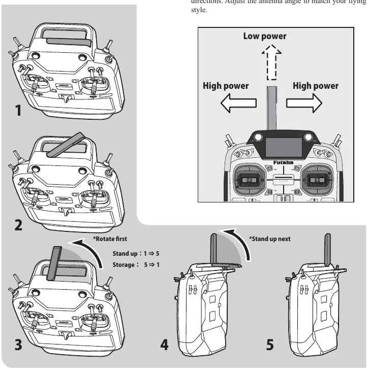
- Antenna Handling: Do not touch the antenna during operation. Keep it straight and away from conductive materials like metal or carbon fiber.
- Flying Safety: Always perform a range test before flying. Do not fly near people, power lines, or other radio control fields.
- Fail Safe: Always set the fail-safe function, typically setting the throttle to idle.
Specifications
The T32MZ-WC operates on the 2.4 GHz band with 100 mW EIRP. It is powered by a 3.8V Li-polymer battery. Compatible receivers include R7208SB, R7308SB, and R7214SB.
Practical help
Common problems
Transmitter screen freezes
Remove and reinsert the battery to force a cold restart.
Receiver not linking
Ensure transmitter is in link mode and within 50cm of the receiver.
Battery not charging
Ensure the AC adapter is connected to an outlet and the transmitter is OFF.
Before use
- Check battery levels for both transmitter and receiver.
- Ensure throttle stick is at minimum (idle) position before turning on.
- Verify all control surfaces and switches function correctly.
- Perform a range test before flying.
- Ensure the antenna is positioned correctly.
Specs in practice
- FASSTest26CH
- High-channel count system for complex models.
- Dual RX Link
- Redundancy system using two receivers.
Images and diagrams
- Antenna positioning: Keep antennas at 90 degrees to each other for optimal signal.
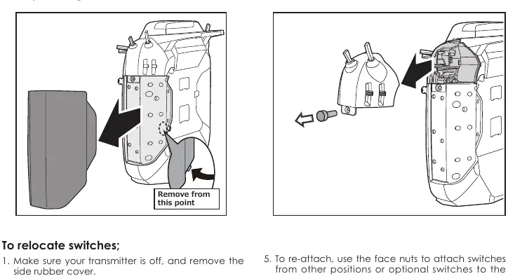
- Switch relocation: Detailed steps for removing and re-attaching switch blocks.
Model compatibility
- FASSTest26CH requires specific receiver versions (V2.0+ for R7208SB/R7308SB).
- Analog servos may not be used in FASSTest 12CH mode.

Manual page author
Michael Turner
Technical manual editor
Reviews PDF manuals for structure, safety notes, and practical product details so readers can find the right information quickly.