Electronics / Marine Navigation
Installation Guide for Garmin ECHOMAP ULTRA 2 16XSV
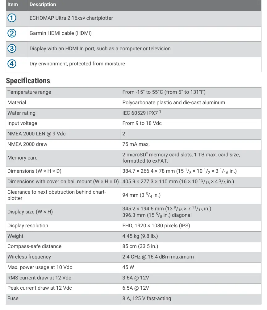
Complete installation guide for the Garmin ECHOMAP ULTRA 2 16XSV chartplotter. Includes step-by-step instructions for bail and flush mounting, wiring diagrams, connector details, and technical specifications.
Quick answers from the manual
Quick answer
- The Garmin ECHOMAP ULTRA 2 16XSV is a chartplotter that can be installed using either a bail mount or a flush mount. It requires a 9-18 Vdc power source and supports various connections including NMEA 2000, HDMI, and Garmin network devices. p. 1, 2, 3, 4
Key actions
- Bail Mounting p. 3
- Flush Mounting p. 4
First start
- Ensure the device is properly grounded and connected to a 9-18 Vdc power source. p. 1, 8
Problems and fixes
Device behaves erratically
Check if the cable connector is fully seated in the port.
p. 5Technical specifications
| Parameter | Value | Meaning | Pages |
|---|---|---|---|
| Input voltage | 9 to 18 Vdc | Operating voltage range | p. 8 |
| Water rating | IPX7 | Water resistance rating | p. 8 |
Where to find it in the PDF
- Safety and Tools p. 1
- Connector View p. 2
- Bail Mounting p. 3
- Flush Mounting p. 4
- Specifications p. 8
Table of contents
Manual images
Click an image to enlargeQuick Guide
This document provides installation instructions for the Garmin ECHOMAP ULTRA 2 16XSV chartplotter. Before beginning, ensure you have the necessary tools: a drill, drill bits (3mm for bail mount; 3.2mm and 8.5mm for flush mount), a #2 Phillips screwdriver, a jigsaw or rotary tool, file, sandpaper, and optional marine sealant. Always wear safety goggles, ear protection, and a dust mask when drilling or cutting.
Mounting the Device
You can mount the device using either a bail mount or a flush mount.
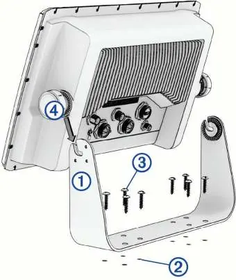
Bail Mounting
- Use the bail-mount bracket as a template to mark the pilot holes.
- Drill the pilot holes using a 3 mm drill bit.
- Secure the bracket to the surface using the included washers and wood screws.
- Install the bail-mount knobs on the sides of the device.
- Place the device in the bracket and tighten the knobs.
- Snap the trim caps into place around the edges of the device.
Note: If mounting on fiberglass, use a countersink bit to drill a clearance counterbore through the top gel-coat layer to prevent cracking.
Flush Mounting
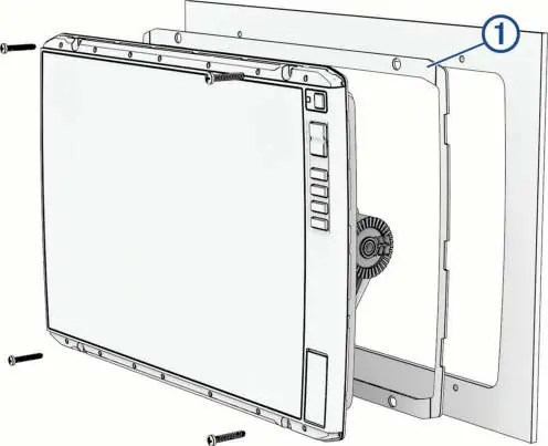
- Secure the flush-mount template to the desired location.
- Drill 8.5 mm holes inside the corners of the template line to prepare for cutting.
- Cut the mounting surface along the inside of the solid line.
- Test the fit of the device in the cutout and refine with a file or sandpaper if necessary.
- Remove the trim caps using a plastic pry tool.
- Align the device with the pilot holes, drill 3.2 mm holes if needed, and install the rubber gasket on the back of the device.
- Connect all cables before placing the device into the cutout.
- Secure the device to the surface with the included screws and snap the trim caps back on.
Connections
The device features several ports on the back, including Power, 12-pin transducer, HDMI video out, Network, and NMEA 2000. Always tighten the locking rings to secure cables. Cover unused connectors with weather caps to prevent corrosion.
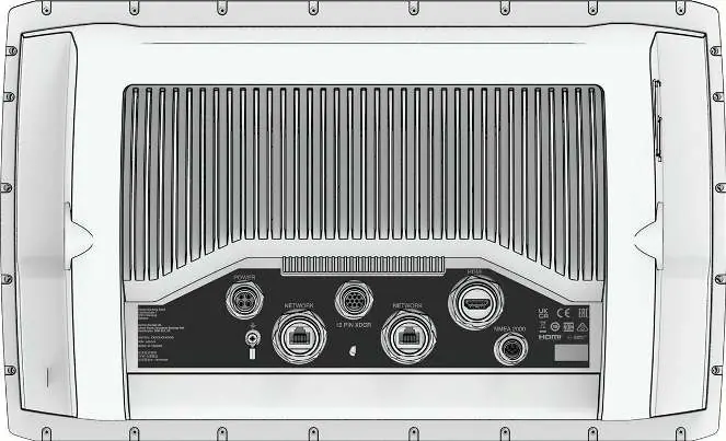
Network and NMEA 2000
The NETWORK port is for connecting compatible Garmin devices like LiveScope or GCV sonar modules. It is not compatible with Garmin BlueNet or Garmin Marine Network. Use only Garmin network cables. The NMEA 2000 port connects to a standard NMEA 2000 network to share data from compatible devices like GPS antennas or VHF radios.
Specifications
- Input Voltage: 9 to 18 Vdc
- Water Rating: IEC 60529 IPX7 (withstands incidental exposure to water up to 1m for 30 min)
- Memory Card: 2 microSD slots, 1 TB max, exFAT format
- Display Resolution: FHD, 1920 x 1080 pixels (IPS)
- Compass-safe Distance: 85 cm (33.5 in.)
- Max Power Usage: 45 W at 10 Vdc
Manufacturer information
Garmin Ltd.
Practical help
Common problems
Device behaves erratically
The cable connector may not be fully seated. Disconnect, check pin alignment, and firmly push the connector into the port.
Gel-coat cracking during mounting
Use a countersink bit to drill a clearance counterbore through the top gel-coat layer before tightening screws.
Corrosion on metal contacts
Cover unused connectors with the attached weather caps.
Before use
- Verify mounting location has a clear view of the screen and access to keys.
- Ensure mounting surface is sturdy enough to support the device.
- Check that cables are long enough to connect components.
- Ensure the device is not installed closer to a compass than the compass-safe distance (85 cm).
- Disconnect the vessel's power supply before beginning installation.
- Wear safety goggles, ear protection, and a dust mask.
Specs in practice
- Compass-safe distance
- The minimum distance (85 cm) the device must be from a magnetic compass to avoid interference.
- Input voltage
- The device operates on a power supply between 9 and 18 Vdc.
Images and diagrams
- Connector View: Identifies the location of Power, 12-pin transducer, HDMI, Network, and NMEA 2000 ports.
- Bail Mount: Illustrates the bracket, pilot hole marking, and knob attachment sequence.
- Flush Mount: Shows the template alignment, cutout process, and rubber gasket placement.
Model compatibility
- Not compatible with Garmin BlueNet or Garmin Marine Network.
- Do not use third-party CAT5e or CAT6 Ethernet cables and RJ45 connectors for the network port.
- Requires Garmin accessory cables for HDMI connections to avoid warranty voiding.

Manual page author
Emily Carter
User documentation editor
Prepares concise manual descriptions and highlights the most useful setup, operation, and maintenance information for readers.