Electronics / Marine Navigation
Installation Manual for Garmin GTR 200/200B COM Transceiver
Comprehensive installation guide for the Garmin GTR 200/200B COM Transceiver, covering mounting, wiring, configuration, and system checkout procedures.
Quick answers from the manual
Quick answer
- The GTR 200/200B is an aviation COM transceiver. This manual provides instructions for installation, wiring, configuration, and testing in an aircraft. p. 1, 10
Key actions
- Access Configuration Mode p. 25
- Update Software p. 42
Problems and fixes
LO VOLT indicator in COM Tests
Indicates low battery or wiring fault; correct before proceeding.
p. 36Maintenance and reset
- Disable Bluetooth (GTR 200B) p. 44
Technical specifications
| Parameter | Value | Meaning | Pages |
|---|---|---|---|
| Output Power | 10 Watts | Carrier minimum | p. 12 |
Where to find it in the PDF
- General Description p. 10
- Installation Procedures p. 22
- Connector Pinout p. 45
Table of contents
Manual images
Click an image to enlargeQuick guide from the manual
This manual provides the necessary mechanical and electrical information for planning and installing the Garmin GTR 200/200B COM Transceiver into an aircraft. It is intended for professional installers and includes detailed wiring, mounting, and configuration procedures.
Equipment Description
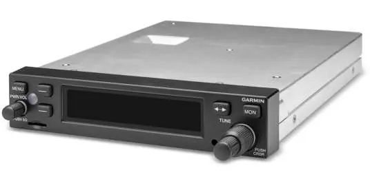
The GTR 200/200B is a COM transceiver designed for aircraft installation. The GTR 200B model includes Bluetooth connectivity for music and phone calls. The unit features a sunlight-readable LCD display and requires a 50-ohm vertically polarized antenna.
Installation Overview
- Antenna: Must be mounted on a metal surface or ground plane (min 18x18 inches), at least 6 feet from other COM/DME antennas.
- Mounting: Designed for avionics stack mounting. Ensure the rack is flush with the panel and not obstructed.
- Cabling: Use shielded wire (MIL-C-27500 or equivalent) and keep runs as short and direct as possible. Avoid routing near high-voltage sources or power lines.
Installation Procedures
- Unpacking: Inspect for shipping damage.
- Wiring Harness: Fabricate cables using the 37-pin D-sub connector (P2001) and BNC antenna connector (P2002).
- Backshell Assembly: Follow Appendix A for shield block and ground assembly instructions.
- Mounting: Install the rack in the instrument panel using #6-32 flat head screws.
- Configuration: Access Configuration Mode by holding the SMALL knob while powering on the unit.
Configuration Mode
Configuration mode allows for setting up specific installation parameters:
- COM Setup: Adjust sidetone, mic gain, and RF squelch.
- Audio Setup: Configure intercom, auxiliary inputs, and receiver output gain.
- Softkey Setup: Customize softkey functions.
- Discrete Setup: Configure discrete inputs (e.g., PTT, frequency swap).
- Lighting Setup: Configure bezel and display lighting source (sensor or bus voltage).
Connector Pinout Information
The J2001 connector provides all electrical interfaces, including:
- Power: Pins 1 (Power) and 20 (Ground).
- Audio: Pilot/Copilot headset and mic inputs, music inputs, and receiver audio output.
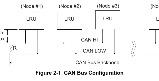
- Data: CAN bus (Pins 6, 7) and RS-232 (Pins 23, 24).
- Discrete: PTT inputs, TX Interlock, and configurable discrete inputs.
Software Updates
Software can be updated using a 4GB micro SD card. Insert the card into the unit face, power on, and follow the on-screen prompts to scan and update the system software.
Safety and Regulatory
The unit contains chemicals known to cause cancer/reproductive harm (California Prop 65). Clean the display only with a microfiber cloth and approved eyeglass lens cleaner; do not use ammonia-based cleaners.
Manufacturer information
Garmin Ltd.
Practical help
Common problems
Low sidetone volume
Adjust the SIDETONE setting in the COM Setup page (range 0-10).
Transmitter sounds weak
Adjust the MIC GAIN setting in the COM Setup page (range 0-10).
Interference or noise
Ensure single-point grounding, isolate audio jacks, and shield the wiring harness.
Unit not seating in rack
Ensure no screw heads or obstructions prevent engagement; check rack installation per Figure C-4.
Before use
- Verify wiring continuity
- Check antenna VSWR (should be < 2:1)
- Ensure proper power and ground connections
- Verify headset configuration (stereo/mono)
- Perform post-installation flight checks
Specs in practice
- Input Voltage
- 14/28 VDC
- Operating Temperature
- -20°C to +55°C
- Frequency Range
- 118.000 to 136.975 MHz
- Output Power
- 10 Watts carrier minimum
Images and diagrams
- Figure 3-1: Front panel controls and knobs
- Figure 4-1: J2001 connector pinout diagram
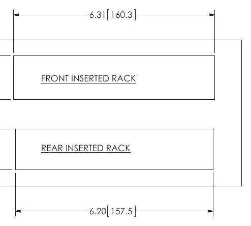
- Figure C-1: Outline dimensions for installation
- Figure D-2: Interconnect example for GDU 37X/46X
Model compatibility
- GTR 200B includes Bluetooth connectivity
- Requires 50 ohm vertically polarized antenna
- Compatible with G3X system via CAN bus or RS-232

Manual page author
Michael Turner
Technical manual editor
Reviews PDF manuals for structure, safety notes, and practical product details so readers can find the right information quickly.