HVAC / Heaters & Fireplaces
Service Manual for Gazco eStudio 85R, 105R, and 135R Electric Fire
Comprehensive service and maintenance guide for Gazco eStudio 85R, 105R, and 135R electric fires. Includes remote pairing, fuel bed access, component replacement procedures, wiring diagrams, and spare parts lists.
Table of contents
Manual images
Click an image to enlargeImportant Service Information
This document provides servicing instructions for the Gazco eStudio LED Electric Fire range, including models 85R, 105R, and 135R. All service operations must be performed by qualified personnel. Ensure the unit is disconnected from the power supply before attempting any maintenance or component replacement.
Pairing the Remote Control
If the unit cannot be controlled by the remote or if you are replacing the remote, follow these steps:
- Locate the reset button on the control panel on the right-hand side of the unit.
- Press and hold the reset button for 3 seconds until the unit emits 3 short beeps.
- Release the button.
- Within 10 seconds, press the power button on the remote control.
- The coding is complete when the unit emits 1 long beep.
If the appliance operates incorrectly due to external interference, reset the remote by opening the back cover and pressing the internal Reset button for 3 seconds.
Accessing and Removing the Fuel Bed
To access the fuel bed for maintenance or cleaning:
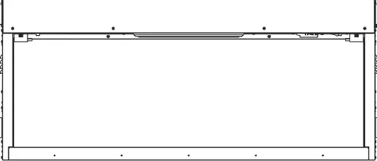
- Follow the specific steps to remove the glass or front panel as required by your installation.
- The fuel bed can be accessed by releasing the retaining screws or clips as shown in the diagrams.
- For full removal, unscrew the fuel bed assembly from the chassis.
When reassembling, ensure the glass embers and logs are placed according to the layout diagrams provided in the manual to maintain the intended flame effect.
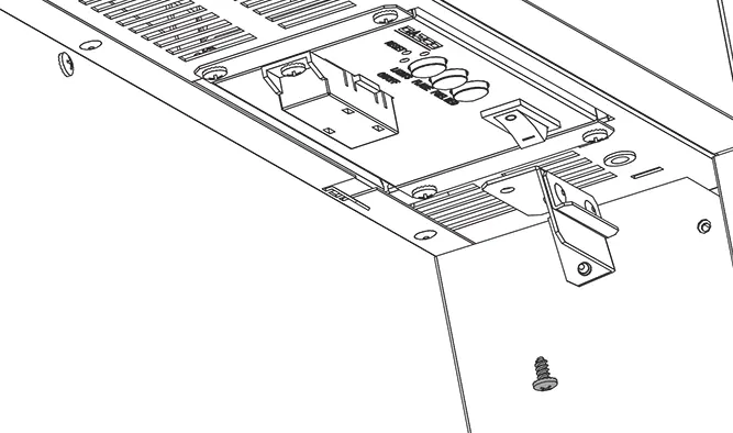
Component Replacement
The manual provides step-by-step procedures for replacing the following components:
- Fuel Bed LEDs: Access the fuel bed, disconnect the LED board connectors, and replace the boards.
- Flame Effect Motor: Remove the flame effect assembly to access and replace the motor.
- Heater Unit: Disconnect the heater assembly from the chassis and replace.
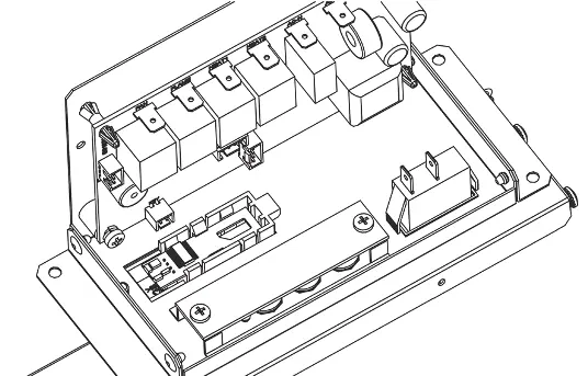
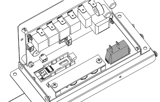
- Control Unit and PCB: Remove the control panel housing to access the main PCB and button board.
Always ensure all electrical connections are secure and correctly routed after replacement.
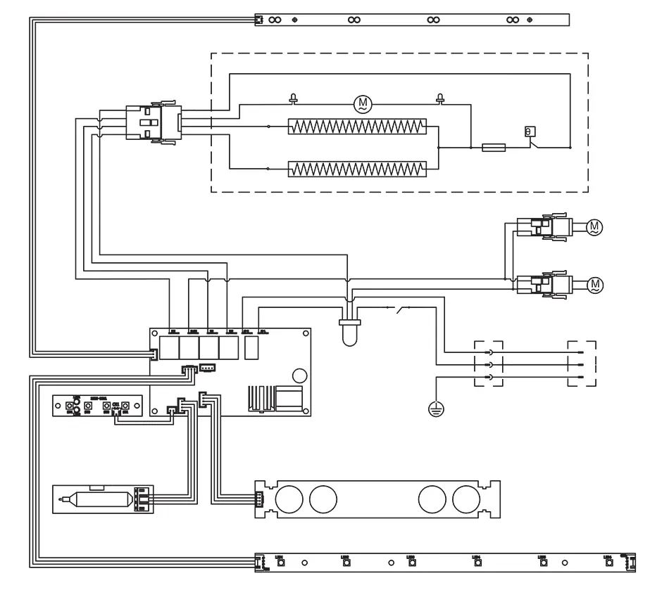
Wiring Diagram
The wiring diagram illustrates the connections between the main PCB, heater, motors, and LED boards. Ensure all connections match the diagram before powering on the unit after any service work.
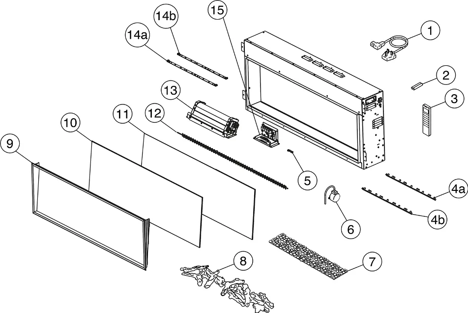
Spare Parts
Refer to the spare parts list for specific part codes for the 85R, 105R, and 135R models. When ordering parts, always quote the correct part code and model number to ensure compatibility.
Practical help
Common problems
Remote control not pairing or unit not responding
Perform the pairing procedure: Press the reset button on the unit for 3 seconds, then press the power button on the remote within 10 seconds.
Appliance operating incorrectly due to external interference
Reset the remote control by opening the back cover and pressing the internal Reset button for 3 seconds.
Before use
- Ensure the unit is disconnected from the power supply before servicing.
- Have a pen or similar tool ready to press the recessed reset button.
- Verify the specific model (85R, 105R, or 135R) to ensure correct spare parts are ordered.
- Check that all electrical connections are secure after any component replacement.
Images and diagrams
- Wiring Diagram: Shows the connections between the PCB, motors, heaters, and LED boards.
- Spare Parts Diagram: Exploded view identifying components by number for ordering.
Model compatibility
- The service procedures apply to the eStudio 85R, 105R, and 135R models.
- Spare parts codes vary by model; check the table on page 30 carefully.

Manual page author
David Miller
Documentation analyst
Organizes user manual content into clear summaries, with attention to model details, product context, and everyday usability.