Plumbing / Sinks Faucets
Assembly Instructions for Hansgrohe AXOR Thermostatic 2-Hole Faucet
Comprehensive assembly and installation guide for Hansgrohe AXOR thermostatic 2-hole faucets. Includes step-by-step mounting instructions, temperature calibration, and parts identification for various series including Starck, Massaud, and...
Quick answers from the manual
Quick answer
- This manual provides assembly and installation instructions for various Hansgrohe AXOR thermostatic 2-hole faucet models. It includes step-by-step visual guides for mounting, handle installation, and temperature calibration. p. 3, 4, 6, 7
Key actions
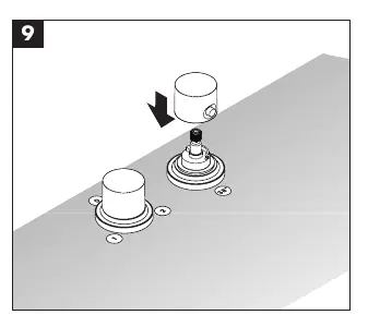
- Install the faucet components p. 3, 6, 8, 10
- Calibrate the water temperature p. 4, 7, 9, 11
First start
- Ensure all components are securely fastened and the water supply is turned on. Check the temperature output and calibrate if necessary. p. 4, 7, 9, 11
Where to find it in the PDF
- Model Overview p. 1
- Installation Instructions p. 3, 4, 5, 6
- Parts List p. 14
Table of contents
Manual images
Click an image to enlargeImportant Information
This manual provides assembly and installation instructions for the Hansgrohe AXOR thermostatic 2-hole faucet series. The document covers multiple models, including Starck, Monteux, Massaud, Carlton, Bouroullec, Steel, Terrano, Uno, and Citterio. Please ensure you follow the specific steps corresponding to your model series.
Installation Overview
The installation process generally involves preparing the faucet base, installing the handle components, and calibrating the water temperature. Ensure the water supply is turned off before beginning any installation work. You will require a hex key (Allen key) in sizes SW 2mm and SW 3mm for assembly and adjustment.
Step-by-Step Assembly
While specific steps vary slightly by model, the general procedure is as follows:
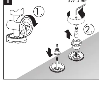

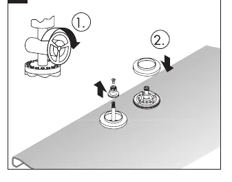
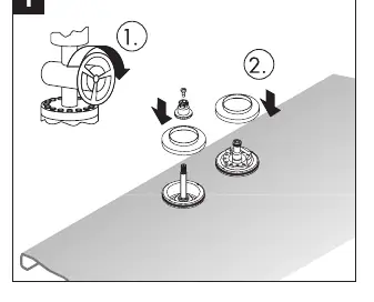
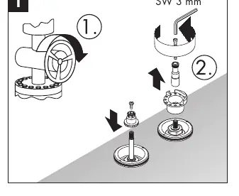
- Preparation: Remove existing handles or components if necessary.
- Mounting: Secure the base components to the installation surface.
- Handle Installation: Attach the handle mechanism using the provided hex key. Ensure the handle is properly aligned and seated.
- Calibration: After installation, verify the water temperature. If the temperature is incorrect, perform the calibration procedure as detailed in the specific section for your model.
Temperature Calibration
Calibration is essential to ensure the thermostatic valve functions correctly. Follow these steps:
- Remove the handle to access the adjustment mechanism.
- Run the water and measure the output temperature using a thermometer.
- Adjust the internal mechanism (often involving turning the cartridge or adjustment screw) until the desired temperature (e.g., 38°C) is achieved.
- Reinstall the handle and secure it with the set screw.
Parts Identification
The manual includes an exploded view of the faucet components. Use this diagram to identify specific parts, such as handles, cartridges, and mounting hardware, when performing maintenance or repairs.
Manufacturer information
Hansgrohe SE
Practical help
Common problems
Incorrect water temperature output
Perform the temperature calibration procedure described in the manual (typically steps 8-10 or 8-11 depending on the model) to adjust the thermostatic valve.
Handle is loose or difficult to operate
Check the set screw on the handle. Use a 2mm or 3mm hex key to tighten or adjust the handle connection.
Before use
- Ensure the main water supply is turned off.
- Verify you have the correct tools: SW 2mm and SW 3mm hex keys.
- Identify your specific faucet model series (e.g., Massaud, Starck) to follow the correct installation steps.
- Check that all components are present and undamaged.
Images and diagrams
- Numbered steps (1, 2, 3...) indicate the sequential order of assembly.
- Steps marked with '= 1', '= 2', or '= 0' indicate specific flow or adjustment settings during calibration.
Model compatibility
- This manual applies to multiple AXOR series. Ensure you are looking at the section specific to your model (e.g., Massaud, Montreux, Bouroullec).

Manual page author
David Miller
Documentation analyst
Organizes user manual content into clear summaries, with attention to model details, product context, and everyday usability.