Toys / RC Models & Drones
HGLRC Zeus VTX PRO 1600mW Video Transmitter User Guide
Quick guide for the HGLRC Zeus VTX PRO 1600mW video transmitter. Includes wiring diagrams, button control instructions, frequency tables, and safety precautions.
Table of contents
Manual images
Click an image to enlargeQuick guide from the manual
The HGLRC Zeus VTX PRO 1600mW is a high-power video transmitter designed for FPV drones. Important: Always ensure the MMCX antenna is securely installed at the output before powering up the unit to prevent damage to internal components. The device supports an input voltage of 7-36V. When operating at high power, the surface temperature can become very high; do not touch it directly with your hands.
Product parameters
- Input Voltage: 7-36V
- BEC Output: 5V/500mA
- Output Power: PIT/25/400/800/1600mW
- Antenna Interface: MMCX
- Protocol: IRC Tramp
- Mounting Hole: 20x20mm, M2
- Weight: 13g
Interface definition
The VTX features the following pinout connections:
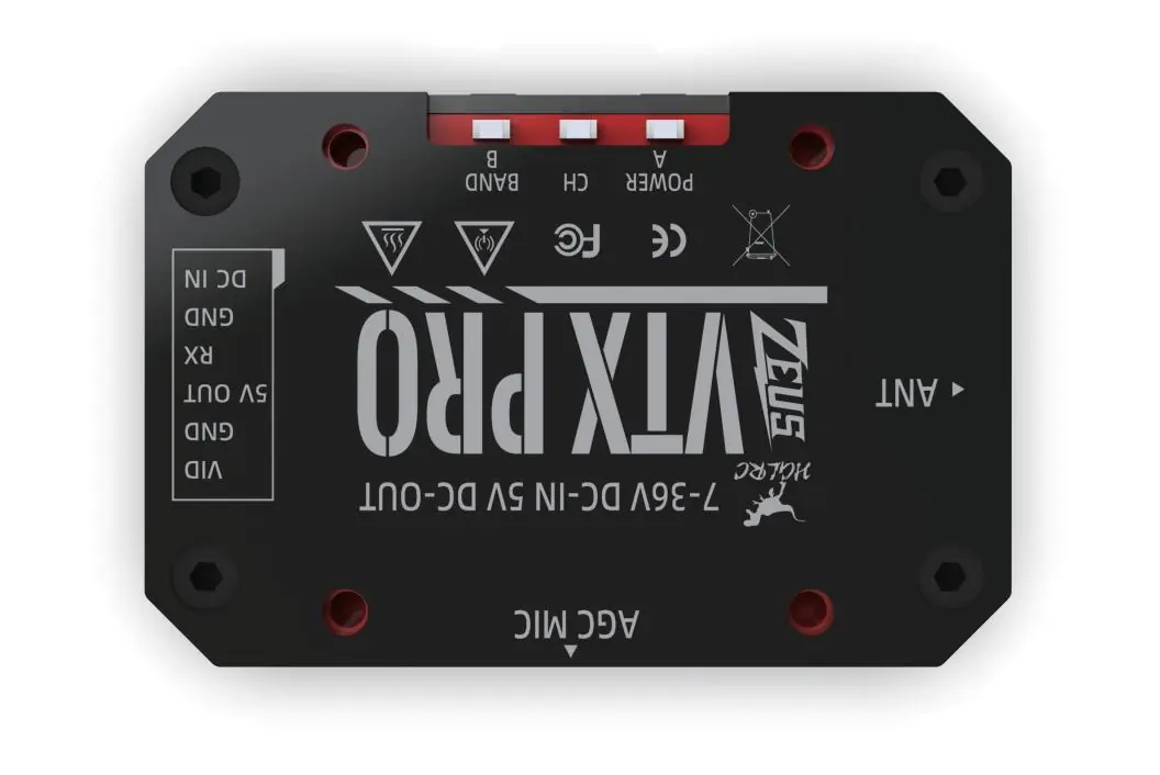
- VID: Video signal input
- GND: Ground
- 5V OUT: 5V power output for camera
- RX: Receiver/Control signal
- GND: Ground
- DC IN: 7-36V Power input
Wiring diagram
Connect the VTX to your flight controller using the provided GH1.25 6Pin cable. Ensure the VID, GND, 5V OUT, RX, and DC IN pins are matched correctly with the corresponding pads on your flight controller.
Function and application description
The VTX parameters can be set via Flight Control OSD (using IRC Tramp protocol) or via the physical buttons on the unit.
Button Controls
- Button A (Short Press): Change VTX Channel (CH).
- Button B (Short Press): Change VTX Band.
- Power Adjustment: Press and hold Button A for 3 seconds or more to cycle through power levels (PIT → 25 → 400 → 800 → 1600mW).
- PIT Mode: Press and hold the "A" button before powering up, then power on the unit to enter PIT mode.
Note: Long presses are not valid for channel/band changes; you must re-power the unit to adjust power if the sequence is interrupted.
Power indicator status
The VTX uses LED indicators to show the current power level:
- PIT: Normal
- 25mW: First blink
- 400mW: Second blink
- 800mW: Third blink
- 1600mW: Fourth blink
Frequency form
The device supports 40 channels across 5 bands (A, B, E, F, R). Frequencies range from 5658MHz to 5917MHz depending on the selected band and channel.
Precautions for use
- Ensure the antenna is installed before powering up.
- Verify input voltage is within the specified 7-36V range.
- Avoid touching the external surface during operation due to high temperatures.
Practical help
Common problems
VTX overheating
Ensure proper airflow around the unit. Do not touch the surface during operation.
No video signal
Check that the MMCX antenna is securely connected and was installed before powering up.
Cannot adjust power
Ensure you are holding the 'A' button for at least 3 seconds. If unsuccessful, power cycle the unit and try again.
Before use
- Install the MMCX antenna before connecting power.
- Verify input voltage is between 7V and 36V.
- Check wiring against the interface definition (VID, GND, 5V, RX, DC IN).
- Ensure mounting holes are aligned (20x20mm).
Specs in practice
- BEC 5V/500mA
- Built-in power output to supply 5V to your FPV camera.
Images and diagrams
- Interface Definition: Shows the pinout for the 6-pin connector.
- Wiring Diagram: Illustrates the connection path between the VTX and the flight controller.
Model compatibility
- Mounting: Compatible with 20x20mm M2 mounting patterns.
- Antenna: Requires MMCX connector.

Manual page author
Emily Carter
User documentation editor
Prepares concise manual descriptions and highlights the most useful setup, operation, and maintenance information for readers.