Lighting / Fixtures
Hinkley 15288TT Taper LED Bollard Installation Guide
Installation and wiring guide for the Hinkley 15288TT Taper LED Bollard. Includes mounting instructions for concrete and wood, wiring diagrams, and LED replacement procedures.
Table of contents
Manual images
Click an image to enlargeQuick Guide
This document provides installation and wiring instructions for the Hinkley 15288TT Taper LED Bollard. The fixture requires a constant current driver and supports both 120VAC and 277VAC installations depending on local codes. Ensure all power is disconnected before beginning installation or maintenance.
Mounting Methods
There are three primary methods for installing the bollard:
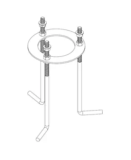
- New Cast in Concrete: Pour concrete for mounting. Assemble lag bolts, hex nuts, and the bottom ring. Place the assembly into the wet concrete, ensuring the bottom ring is even with the surface and the lag bolts sit 2 inches above the concrete. Allow the concrete to set before proceeding.
- Tapcon Drill in Existing Concrete: Use the narrow slots on the mounting plate for Tapcon bolts. Drill into the concrete, bring the power wire through the center of the plate, and secure the assembly.
- Lag Screw into Decking/Wood: Drill into the wood/deck in the center of the plate. Bring the power wire through the deck board gaps and secure the mounting plate using the supplied bolts.
Assembly and Wiring
Once the mounting plate is secured:
- Secure the coupler, hex nut, and mounting rods to the mounting plate.
- Attach the top ring to the mounting rods.
- Route the power wire through the center of the upper ring.
- Slide the bollard enclosure over the mounting hardware, passing the power wire through the fixture.
- Secure the bollard using the brass coupler and washers.
- Connect the power driver and earth ground.
- Slide in the four washboards and secure them with the corner tab and screw.
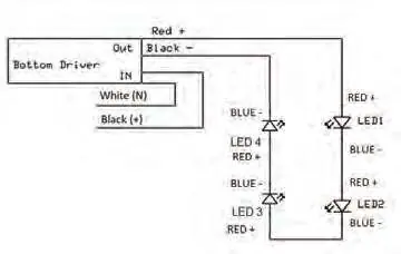
- Wire the washboard to the driver following the circuit diagram. LEDs are connected in series (red to blue).
- Cap off 0-10V dimming wires (purple/grey) if not in use.
- Secure the cover to the bollard with the four screws and o-rings.
LED Replacement
- Turn off power to the fixture.
- Remove the fixture top and washboards.
- Disconnect wire connections between the LED and the driver.
- Remove the screws holding the failed LED in place.
- Use the same screws to secure the replacement LED.
- Make connections between the replacement LED and the driver.
- Restore power to the fixture.
Technical Notes
The fixture is supplied with silicone-filled wire nuts, which are intended for one-time use only. The wire nut capacity is 2 pieces of 18 AWG or 2 pieces of 12 AWG. All four LEDs are wired in series. The driver is programmed to 700mA.
Manufacturer information
Hinkley Lighting
Practical help
Common problems
Mounting plate orientation is incorrect
The orientation of the plate is difficult to adjust after concrete sets. Ensure the plate is aligned correctly before the concrete hardens.
LED failure
Turn off power, remove the top and washboards, disconnect the failed LED, and replace it using the existing screws and wiring connections.
Wiring configuration
Ensure the LEDs are connected in series (red to blue) and the constant current driver is used.
Before use
- Verify the mounting surface (new concrete, existing concrete, or wood).
- Ensure power is turned off at the source.
- Check local codes for wiring requirements (120VAC vs 277VAC).
- Confirm all mounting hardware (bolts, nuts, washers) is present.
- Ensure silicone-filled wire nuts are available for connections.
Specs in practice
- Driver Output
- The driver is programmed to 700mA constant current.
- Wire Nut Capacity
- Supports 2 pieces of 18 AWG or 2 pieces of 12 AWG wire.
- Dimming Wires
- Purple and grey wires are for 0-10V dimming and should be capped if not used.
Images and diagrams
- Drawings 1, 4, 6, and 8 illustrate the assembly sequence of the mounting plate, rods, and couplers.
- The Wiring Diagram shows the serial connection of the four LEDs to the driver.
Model compatibility
- LEDs must be used with a constant current driver.
- Silicone-filled wire nuts are for one-time use only.

Manual page author
David Miller
Documentation analyst
Organizes user manual content into clear summaries, with attention to model details, product context, and everyday usability.