Lighting / Fixtures
Installation Guide for Hinkley 10544MR Foundry Dome LED Outdoor Barn Light
Comprehensive installation and assembly guide for the Hinkley 10544MR Foundry Dome LED Outdoor Barn Light. Includes step-by-step instructions for wiring, mounting, and shade installation.
Table of contents
Manual images
Click an image to enlargeQuick Guide from the Manual
This document provides assembly and installation instructions for the Hinkley Foundry series outdoor light. Key steps include feeding wires through the fixture arm, mounting the bracket to a junction box, making electrical connections, and attaching the shade. Ensure power is turned off at the breaker before beginning installation.
Assembly of the Fixture Arm
Before mounting, the arm must be prepared:
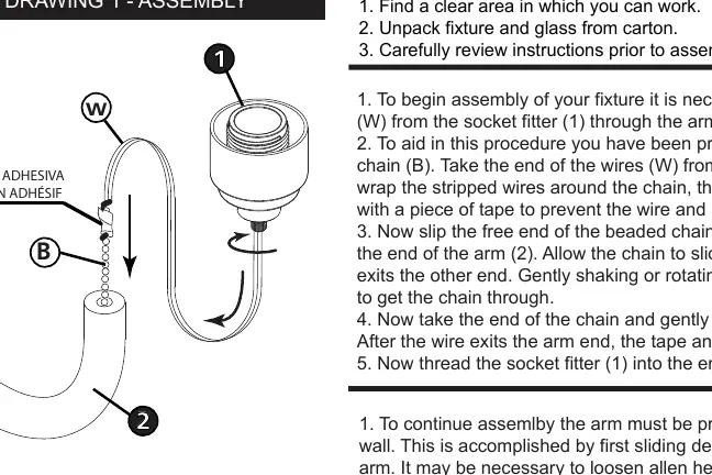
- Feed the wires (W) from the socket fitter (1) through the arm (2). Use the provided beaded chain (B) to pull the wires through the arm by wrapping the wires around the chain and taping them together.
- Once the wires exit the arm, remove the tape and chain.
- Thread the socket fitter (1) into the end of the arm (2).
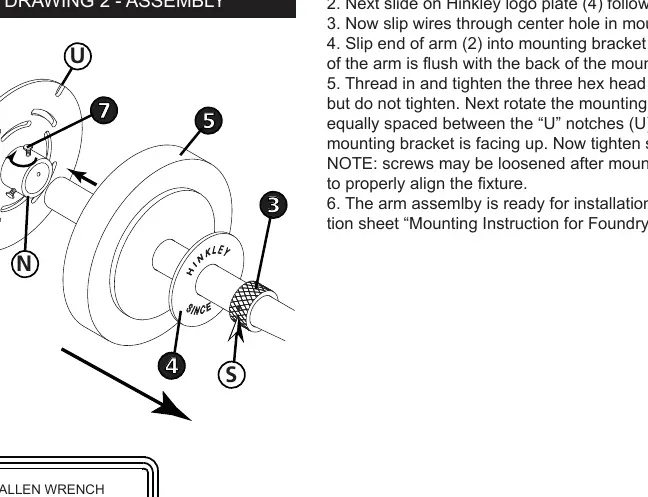
- Slide the decorative collar (3), Hinkley logo plate (4), and canopy (5) onto the arm. If necessary, loosen the Allen head screw (S) to slide the collar.
- Insert the arm (2) into the mounting bracket (6) and tighten the hex head screws (7) to secure.
Mounting to the Wall
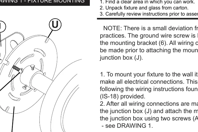
- Make all electrical connections before attaching the mounting bracket (6) to the junction box (J).
- Push all wires into the junction box (J) and attach the mounting bracket (6) using two screws (A).
- If additional support is needed, use the U-shaped notches on the outer edge of the mounting bracket with appropriate hardware.
- Slide the canopy (5), logo plate (4), and collar (3) against the wall and tighten the set screw (S) to secure the assembly.
Shade Installation
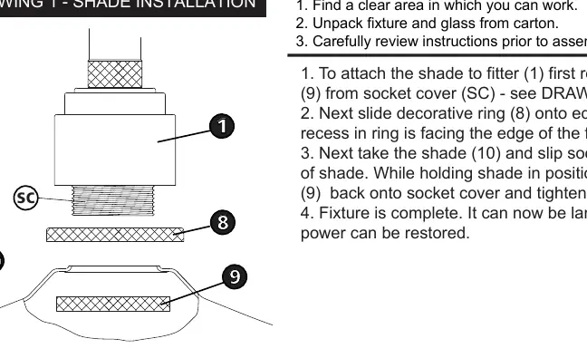
- Remove the knurled shade ring (9) from the socket cover (SC).
- Slide the decorative ring (8) onto the edge of the fitter (1), ensuring the recess faces the fitter edge.
- Place the shade (10) over the socket.
- Thread the shade ring (9) back onto the socket cover and tighten to secure the shade in place.
Wiring and Grounding Instructions
Follow these steps for electrical safety:
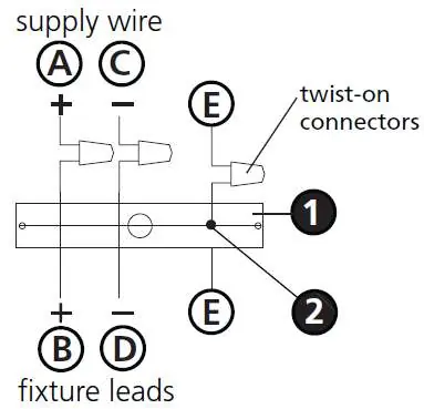
- Positive Wire: Connect the positive supply wire (A) to the positive fixture lead (B) using a twist-on connector.
- Negative Wire: Connect the negative supply wire (C) to the negative fixture lead (D) using a twist-on connector.
- Grounding: Fasten the fixture ground wire (E) to the mounting strap (M) using the ground screw (S) for flush mounts, or connect directly to the building ground system for chain-hung fixtures.
- Outdoor Protection: Cover the open ends of connectors with silicone sealant to create a watertight seal. If installing on a wall, use caulk to seal gaps between the mounting plate and the wall.
Manufacturer information
Hinkley Lighting
Practical help
Common problems
Wires are difficult to feed through the arm
Use the provided beaded chain to pull the wires through. Gently shaking or rotating the tube may help the chain pass through.
Fixture is not flush with the wall
Loosen the hex head screws (7) on the mounting bracket to align the fixture, then tighten them securely.
Water entering the outlet box
Use silicone sealant on wire connectors and apply caulk to seal gaps between the fixture mounting plate and the wall.
Before use
- Turn off the power supply at the circuit breaker.
- Ensure you have a clear, clean workspace.
- Verify all parts (shade, collar, canopy, bracket) are unpacked and present.
- Check that the junction box is properly installed and supported.
- Have appropriate tools ready, including an Allen wrench.
Images and diagrams
- Drawing 1 (Page 1): Illustrates the wire feeding process using the beaded chain.
- Drawing 2 (Page 1): Shows the assembly of the arm components including the collar, logo plate, and canopy.
- Drawing 1 (Page 4): Provides the wiring diagram for flush mount fixtures.
Model compatibility
- Requires a standard junction box for mounting.
- Suitable for outdoor use when properly sealed with silicone.

Manual page author
Michael Turner
Technical manual editor
Reviews PDF manuals for structure, safety notes, and practical product details so readers can find the right information quickly.