Electronics / Televisions
Installation and Maintenance Manual for Hisense Hi-Therma Heat Pump Outdoor Unit
Comprehensive installation and maintenance guide for the Hisense Hi-Therma heat pump outdoor unit. Includes safety instructions, piping, electrical wiring, DIP switch configurations, and technical specifications.
Table of contents
Manual images
Click an image to enlargeQuick Guide from the Manual
This manual provides essential instructions for the installation, operation, and maintenance of the Hisense Hi-Therma heat pump outdoor unit. Key procedures include proper site selection, water and refrigerant piping, electrical wiring, and system configuration via DIP switches. Always ensure installation is performed by qualified personnel.
Safety Precautions
The unit uses R32 refrigerant, which is flammable. Strict adherence to safety protocols is required:
- Ensure the installation area is well-ventilated.
- Keep ignition sources away from the unit.
- Do not mix the unit with general household waste at the end of its life; dispose of it according to local regulations.
- Always disconnect the power supply before performing any maintenance or electrical work.
- Ensure the unit is properly grounded.
Installation and Handling
Proper placement is critical for system performance and safety:
- Install the unit in a shaded area, away from direct sunlight and heat sources.
- Ensure the foundation is solid and stable.
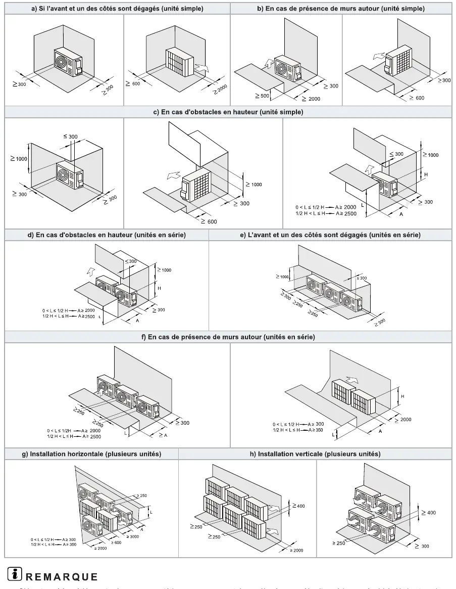
- Maintain required clearances around the unit to ensure proper airflow and maintenance access.
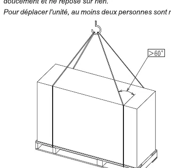
- Use appropriate lifting equipment and ensure the unit remains stable during transport.
Water Piping and Connections
The water circuit must be installed correctly to prevent leaks and ensure efficiency:
- Install a water filter at the inlet to protect the heat exchanger.
- Use flexible joints to minimize vibration.
- Ensure all connections are tight and leak-free.
- The system must be filled and purged of air before operation.
- Check water pressure; the operating range is typically 1 to 3 bar.
Electrical Wiring and Configuration
Electrical work must comply with local regulations:
- Verify the power supply voltage and frequency match the unit specifications.
- Use appropriate cable sizes and circuit breakers as specified in the manual.
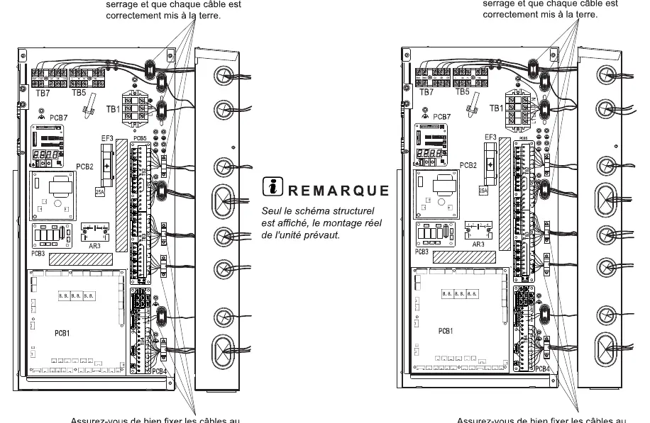
- Ensure all electrical connections are secure and properly grounded.
- Configure the system using the DIP switches on the PCB (Printed Circuit Board) to set unit capacity, pump operation, and emergency modes.
Test Run and Maintenance
Before starting the system, perform a thorough check:
- Verify all electrical connections and grounding.
- Ensure all service valves are fully open.
- Check that the water circuit is filled and air is purged.
- Perform a test run to ensure the system operates correctly.
- Regularly inspect the unit for leaks, debris, and proper ventilation.
Manufacturer information
Hisense
Practical help
Common problems
System fails to start
Check power supply, voltage, and ensure all electrical connections are secure. Verify DIP switch settings.
Water leakage
Inspect pipe connections, ensure seals are intact, and check drainage system.
Refrigerant leak
Stop operation immediately, ventilate the area, and contact authorized service personnel.
Before use
- Verify power supply voltage and frequency.
- Ensure all electrical connections are tight and grounded.
- Check that all service valves are fully open.
- Confirm water circuit is filled and purged of air.
- Verify minimum water flow rate.
- Ensure the unit is stable and properly mounted.
Specs in practice
- GWP (Global Warming Potential)
- R32 refrigerant has a GWP of 675.
- Water Pressure
- Operating range is 1 to 3 bar.
- Power Supply
- 220-240V or 380-415V depending on the specific model.
Images and diagrams
- DIP Switch Settings: Used to configure unit capacity, pump operation, and emergency modes.
- Water Piping: Shows connections for heating, cooling, and DHW circuits.
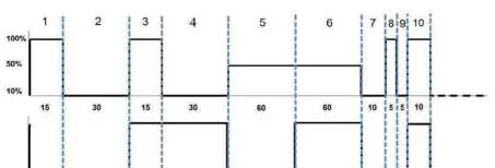
- Pump Purge Cycle: Illustrates the timing sequence for air purging.
Model compatibility
- Compatible with R32 refrigerant only.
- Requires professional installation by qualified personnel.
- Not for use with indoor units other than specified Hi-Therma systems.

Manual page author
Michael Turner
Technical manual editor
Reviews PDF manuals for structure, safety notes, and practical product details so readers can find the right information quickly.