Tools / Saws
User Manual for Holzmann BS 128HDR Metal Band Saw
Quick guide for the Holzmann BS 128HDR metal band saw. Includes assembly instructions, operation steps, blade speed settings, maintenance, and troubleshooting.
Table of contents
Manual images
Click an image to enlargeQuick guide from the manual
The Holzmann BS 128HDR is a metal band saw designed for cutting metals and plastics. Before first use, ensure the machine is placed on a level surface with at least 0.8m of clearance around it. Always wear protective equipment, including safety glasses and protective clothing. Never operate the machine unattended or with loose jewelry/clothing. Ensure the machine is properly grounded before connecting to the power supply.
Components and Controls
The machine features a main body, motor, hydraulic clamping cylinder for feed adjustment, miter angle clamping screw, lifting handle, vice handwheel, saw belt clamping screw, emergency switch, and a band tension adjustment knob.
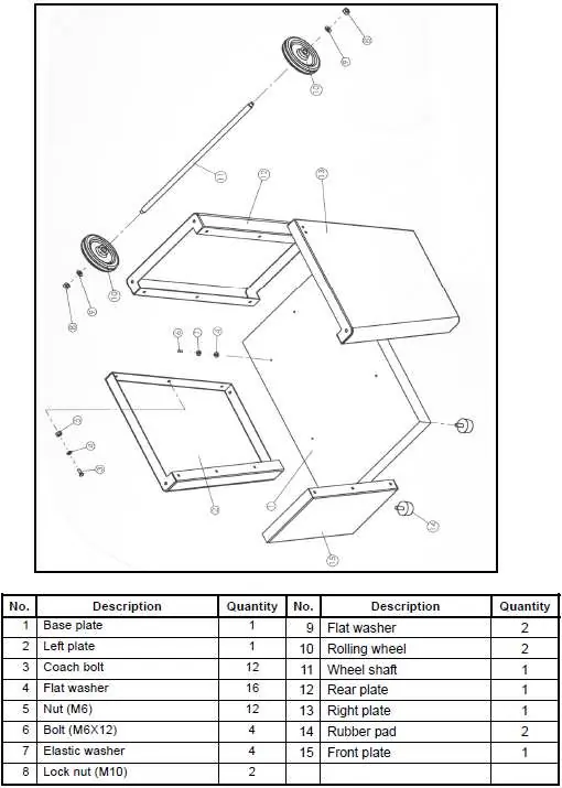
Assembly
The machine is largely pre-assembled. To complete the setup: 1. Mount the wheels to the undercarriage. 2. Assemble the base and attach it to the chassis. 3. Place the band saw on the base and fasten it securely with screws. 4. Screw the spring bracket onto the console as indicated in the manual.

Operation
Before starting, ensure all components are in good working order, the correct blade speed is set for the material, the workpiece is clamped at the correct angle, and the saw arm is pivoted up. To operate: 1. Turn on the machine using the ON/OFF switch. 2. The automatic feed moves the saw arm downwards. 3. Do not apply manual pressure; let the saw arm work by its own weight. 4. The machine switches off automatically after the cut.
Blade Speed and Tension
Blade speed is adjusted via the belt drive. Refer to the speed table in the lid to select the correct belt position (A-F) based on the material (Stainless Steel, Structural Steel, or Brass/Aluminium). Ensure the blade is tensioned correctly (2-3mm test) using the control knob.
Maintenance and Care
Disconnect from power before any maintenance. Clean the machine after each shift using suction or compressed air. Lubricate moving joints every 100 working hours with a thin layer of oil or grease. The transmission runs in an oil bath and requires an oil change approximately once per year. If the blade does not run straight, adjust the tape/camber using the grub screw on the impeller housing.
Troubleshooting
If the machine does not start, check the power connection, fuse, and cable. If the machine vibrates, check for uneven ground, loose motor mounting, or a worn belt tension spring. For bad cuts, check if the feed is too fast or the blade is loose.
Practical help
Common problems
Machine does not start
Check if the machine is connected, inspect the fuse/contactor, and ensure the cable is not damaged.
Bandsaw is not on speed
Check if the extension cord is too long, verify the motor is suitable for the voltage, or contact an electrician regarding the power grid.
Machine vibrates strongly
Ensure the machine is on even ground, tighten motor mounting screws, or replace the belt tension spring.
Bad cuts
Select a lower feed rate and ensure the bandsaw blade is properly tightened.
Before use
- Check that all machine components are in good working order.
- Set the correct blade speed for the material.
- Clamp the workpiece at the correct angle.
- Ensure the workpiece rests safely.
- Verify the saw band is set correctly (tension and vertical alignment).
- Ensure the saw arm is pivoted up.
- Remove any tools from the machine bed.
Specs in practice
- Cutting speeds
- 23, 34, 54 m/min
- Blade dimensions
- 1640 x 13 x 0.6 mm
- Max round profile at 90°
- 125 mm
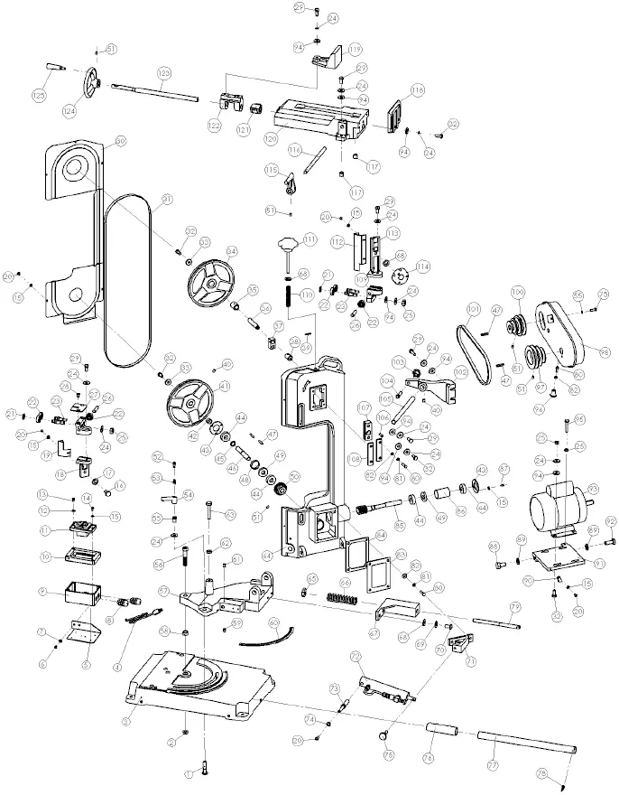
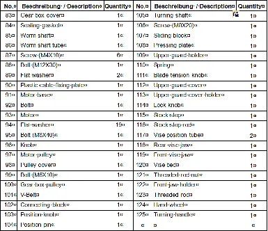
Images and diagrams
- Components and Controls: Identifies the main body, motor, hydraulic cylinder, vice, and switches.
- Wiring Diagram: Shows electrical connections for 230V and 400V configurations.
- Exploded View: Detailed breakdown of all machine parts for spare part identification.
Model compatibility
- Designed exclusively for cutting metals and plastics.
- Not intended for outdoor use.
- Requires a grounded electrical outlet.
- Do not use for cooling magnesium with oils or emulsions.

Manual page author
Emily Carter
User documentation editor
Prepares concise manual descriptions and highlights the most useful setup, operation, and maintenance information for readers.