Electronics / Fire Alarm Systems
Quick Reference Guide for Honeywell Flame Detectors and Test Lamps
A quick reference guide for the installation and safety of Honeywell Flame Detectors and Test Lamps in hazardous locations. Includes mounting instructions, wiring guidelines, electrical ratings, and safety warnings.
Quick answers from the manual
Quick answer
- This guide provides installation and safety instructions for Honeywell Flame Detectors and Test Lamps in hazardous locations, including mounting steps, wiring requirements, and electrical ratings. p. 1, 2
Key actions
- Mount the detector using 1/4-20 or M6 fasteners, angled at least 40 degrees down. p. 2
- Connect wiring via 3/4 inch NPT or M25 openings using shielded cable. p. 2
Problems and fixes
Improper flame detection
Review mounting area, ensure unobstructed view, angle down at 40 degrees, and avoid direct sunlight/radiation.
p. 1Maintenance and reset
- Do not service parts inside the electronics module; replace the module if necessary. p. 1
Technical specifications
| Parameter | Value | Meaning | Pages |
|---|---|---|---|
| FS10 | 12 VDC, 60 mA | Electrical rating | p. 2 |
| FS20X/FS24X | Max 32 VDC, 150 mA | Electrical rating | p. 2 |
Where to find it in the PDF
- Safety Warnings and Installation Overview p. 1
- Installation Steps and Electrical Ratings p. 2
Table of contents
Quick guide from the manual
This document provides essential installation and safety information for Honeywell Flame Detectors and Test Lamps designed for hazardous locations. It covers mounting, wiring, and electrical specifications required for proper operation.
Safety Warnings
Risk of Improper Flame Detection:
- Install only in areas matching environmental and hazardous area ratings.
- Ensure an unobstructed view and optimal angle (at least 40 degrees down from horizontal).
- Avoid direct sunlight into the detector window; use the provided sunshade.
- Use shielded cable for all wiring and ground the shield at one end.
- Keep devices away from mercury vapor lights, variable speed drives, and radio repeaters.
- Do not touch the sensors on the front of the electronics module.
Risk of Explosion:
- Ensure power is off and no hazardous gases or dusts are present before installing or opening the device.
- Use only hazardous location-approved plugs (M25 or 3/4 inch NPT).
- Do not connect test lamps to external power sources; they are battery-operated only.
Risk of Product Damage:
- Do not install in areas with high mechanical damage risk.
- Seal conduit entries with thread sealant (e.g., Loctite 565) to maintain IPX6 integrity.
Installation Procedure
- Mounting: Securely mount the detector using minimum 1/4-20 or M6 sized fasteners. It is recommended to angle detectors down at least 40 degrees from horizontal.
- Accessing Module: Loosen the set screw on the cover assembly, then loosen the 3 Philips screws to remove the electro-optical Detector Module. Place it in a safe location.
- Wiring: Connect the cable gland or conduit to the detector enclosure via the 3/4 inch NPT or M25 openings. Connect wires rated for at least 85°C according to the wiring diagram on the cover. Ensure the enclosure is properly grounded.
- Configuration: Configure the device according to the product's User Manual and Performance Appendix.
- Closing: Reconnect the field connectors, secure the module with Philips screws, and install the cover. Ensure the O-ring is compressed and tighten the cap screw.
- Testing: Perform a rough Field of View (FoV) adjustment and test functionality/communication in the final system.
Electrical Ratings
- Test Lamps (battery powered): 12 VDC, 600 mA
- FS10: 12 VDC, 60 mA
- FS10-R-A: Max 29 VDC, 120 mA; Relay 24 VDC, 1 A
- FS20X and FS24X Series: Max 32 VDC, 150 mA; Relay 24 VDC, 1 A
- FS20XP and FS24XP: 18-32 VDC, 500 mA max; Relay 24 VDC/AC, 2 A maximum
Manufacturer information
Honeywell International Inc.
Practical help
Common problems
Improper flame detection
Ensure the detector is angled at least 40 degrees down, has an unobstructed view, and is shielded from direct sunlight or rapid light modulation.
Loss of IPX6 integrity
Ensure all conduit entries are sealed with thread sealant such as Loctite 565 or an approved equivalent.
Explosion risk during maintenance
Ensure power is off and no hazardous gases or dusts are present before opening the device.
Before use
- Verify hazardous area ratings for the installation site.
- Ensure power is disconnected.
- Check that no hazardous gases or dusts are present.
- Use shielded cable for all communications.
- Ensure proper grounding in accordance with local codes.
- Verify that conduit entries are properly sealed.
Specs in practice
- FS20XP/FS24XP
- Flame detector series requiring 18-32 VDC, 500 mA max.
Images and diagrams
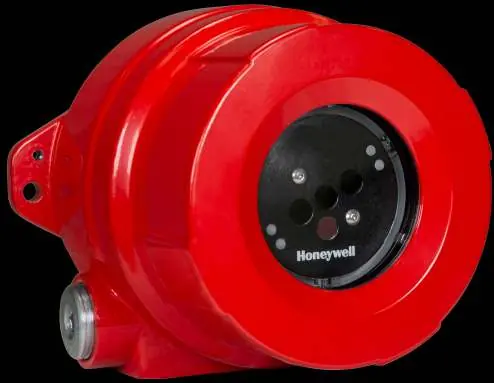
- The device features a flameproof and explosion-proof enclosure.
- The electro-optical module is removable for wiring access.
- Nameplates indicate specific regional approvals and electrical ratings.
Model compatibility
- Approved for use in Class 1 and Zone 1 environments.
- Requires 1/4-20 or M6 fasteners for mounting.
- Requires 3/4 inch NPT or M25 conduit openings.

Manual page author
Michael Turner
Technical manual editor
Reviews PDF manuals for structure, safety notes, and practical product details so readers can find the right information quickly.