Home / Security
Installation Guide for Honeywell 201052A/B Auxiliary Switch
Installation and configuration guide for the Honeywell 201052A and 201052B Auxiliary Switches. Includes wiring, switching configuration, and calibration steps for ML6161/ML7161 actuators.
Quick answers from the manual
Quick answer
- The 201052A/B is an auxiliary switch for ML6161/ML7161 actuators, allowing control of external equipment at specific actuator stroke points (0-90°). p. 1
Key actions
- Mounting the switch p. 2
- Adjusting the cam p. 2
First start
- Disconnect power, mount the switch, engage declutch to rotate hub, and adjust cam position. p. 1, 2
Problems and fixes
Actuator gear damage
Always depress the declutch button when manually turning the hub.
p. 1Technical specifications
| Parameter | Value | Meaning | Pages |
|---|---|---|---|
| Electrical Ratings | 50 VA, 24 Vac | Pilot duty, selective not simultaneous. | p. 1 |
| Switch Differential | 3 degrees | Maximum angular degrees. | p. 1 |
Where to find it in the PDF
- Installation and Application p. 1
- Switching Configuration and Calibration p. 2
Table of contents
Manual images
Click an image to enlargeQuick guide from the manual
The Honeywell 201052A/B Auxiliary Switch is designed for use with ML6161/ML7161 Direct Coupled Actuators. It allows for the control of external equipment, such as electric reheat coils and fans, at an adjustable point in the actuator stroke (0° to 90°). Important: Always disconnect the power supply before installation to prevent electrical shock. When manually turning the actuator hub, you must depress the declutch button to avoid damaging the internal gears.
Installation
The installer must be a trained, experienced service technician. Follow these steps to install the switch:
- Disconnect the power supply to the actuator.
- Align the switch hub with the set screws on the actuator.
- Mount the switch on the actuator and tighten the three captive screws.
- Engage the declutch button and rotate the hub to the desired position for switch operation.
- Disengage the declutch button.
Switching Configuration
The switch can be configured for clockwise (CW) or counterclockwise (CCW) rotation. The cam position determines when the switch activates:
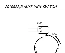
- Counterclockwise rotation: The normally closed contact opens during CCW rotation, and the normally open switch closes.
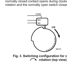
- Clockwise rotation: The normally closed contact opens during CW rotation, and the normally open switch closes.
Adjustment and Calibration
To set the switch activation point:
- Use a screwdriver to move the cam inside the switch assembly to the appropriate position.
- Monitor the switch closure using an ohmmeter to perform a continuity check.
- Ensure the switch activates at the desired degree of stroke.
Note: When installed, the angular position indicator on the switch face moves from 90° to 0° during counterclockwise motion and from 0° to 90° during clockwise motion.
Continuity Measurements
Use an ohmmeter to verify the switch state:
- Switch Activated: Normally Open Contacts = 0 ohms; Normally Closed Contacts = Infinite ohms.
- Switch Not Activated: Normally Open Contacts = Infinite ohms; Normally Closed Contacts = 0 ohms.
Manufacturer information
Honeywell International Inc.
Practical help
Common problems
Internal gear damage
Ensure the declutch button is depressed while manually turning the actuator hub.
Switch not activating at correct stroke point
Adjust the cam position inside the switch assembly using a screwdriver and verify with an ohmmeter.
Before use
- Disconnect power supply before installation.
- Verify compatibility with ML6161/ML7161 Direct Coupled Actuators.
- Determine if you need 201052A (one switch) or 201052B (two switches).
- Have an ohmmeter ready for continuity testing.
- Ensure the installer is a trained, experienced service technician.
Specs in practice
- Electrical Ratings
- 50 VA, pilot duty at 24 Vac (selective, not simultaneous).
- Switch Differential
- Three angular degrees maximum.
Images and diagrams
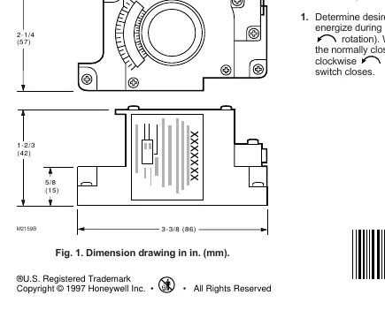
- Fig 1: Provides dimensions for the switch unit.
- Fig 2: Shows switching configuration for counterclockwise rotation.
- Fig 3: Shows switching configuration for clockwise rotation.
- Fig 4: Illustrates mounting the switch onto the ML6161 actuator.
Model compatibility
- Compatible with ML6161/ML7161 Direct Coupled Actuators.

Manual page author
David Miller
Documentation analyst
Organizes user manual content into clear summaries, with attention to model details, product context, and everyday usability.