Toys / RC Models & Drones
User Manual for Horizon Hobby Fw 190A 1.5m RC Airplane
Comprehensive user guide for the Horizon Hobby Fw 190A 1.5m RC airplane. Includes assembly instructions, transmitter setup, binding procedures, SAFE Select configuration, and troubleshooting.
Table of contents
Manual images
Click an image to enlargeQuick Guide from the Manual
This document provides essential setup and operation instructions for the Horizon Hobby Fw 190A 1.5m RC airplane. Before flying, ensure the transmitter is programmed correctly, the battery is fully charged, and the Center of Gravity (CG) is verified. Always perform a control direction test and an AS3X control test before your first flight.
Assembly
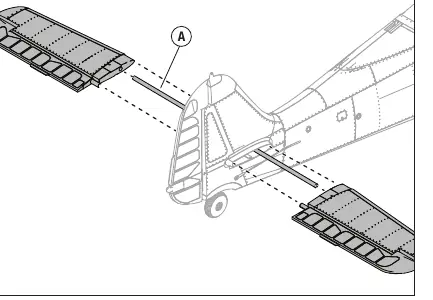
Horizontal Stabilizer: Slide the stabilizer tube into the rear fuselage. Attach the two-piece stabilizer using the provided M3 x 10mm screws. Ensure the control horn faces downward and connect the linkage to the ball link.
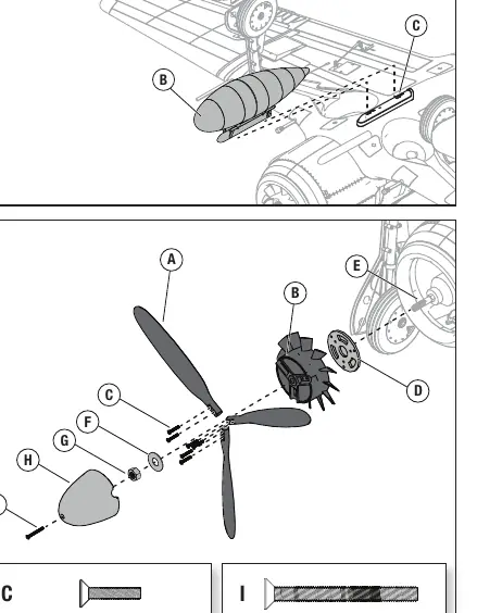
Wing Assembly: Align the servo connections and press the wing into the wing saddle. Secure the wing using the four provided M3 x 32mm screws. Align the wingtips and press them until they click into place.
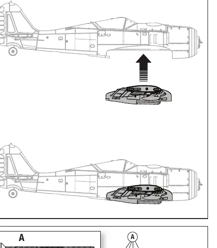
Propeller: Install the aluminum backplate, attach the propeller blades using the six M3 x 16mm screws, and secure the assembly to the propeller shaft. Ensure the spinner is aligned and secured with the M3 x 32mm screw.
Transmitter Setup
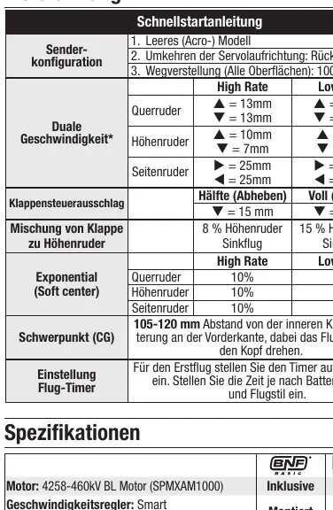
The transmitter must be configured for an Acro model. Set dual rates, exponential values, and flap settings as specified in the quick start table. Ensure the throttle cut function is activated for safety.
Binding and SAFE Select
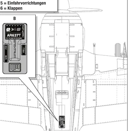
Binding: Ensure the transmitter is programmed. With the battery connected, use the bind button or bind plug to enter bind mode. The receiver LED will flash orange.
SAFE Select: This technology provides flight envelope protection. It can be activated or deactivated during the binding process. You can assign a switch on your transmitter to toggle between SAFE Select and AS3X modes.
Telemetry and AS3X
The aircraft features SMART Technology telemetry. Ensure your transmitter is compatible and updated to view battery and ESC data. The AS3X system provides stabilization; perform the AS3X control test to verify correct operation.
Maintenance
Motor Maintenance: Always disconnect the battery before performing maintenance. To disassemble, remove the spinner, propeller, and cooling fan. Remove the motor mounting screws to detach the motor from the mount.
Troubleshooting: If the aircraft does not bind, check the distance from the transmitter, ensure no large metal objects are nearby, and verify the bind plug is inserted correctly. If the motor pulses or loses power, the Low Voltage Cutoff (LVC) may have been triggered; land immediately and recharge the battery.
Manufacturer information
Horizon Hobby, LLC
Practical help
Common problems
Aircraft does not bind to transmitter
Ensure the transmitter is not too close to the receiver during binding. Remove nearby large metal objects. Verify the bind plug is inserted correctly and the battery is fully charged.
Motor pulses or loses power
The Low Voltage Cutoff (LVC) has been triggered. Land immediately and recharge or replace the battery.
Excessive vibrations
Check for an unbalanced propeller, loose components, or a damaged spinner. Tighten all fasteners.
Control surfaces do not move
Verify the transmitter is bound correctly and the correct model memory is selected. Check for damaged servos or linkages.
Before use
- Charge the flight battery fully.
- Program the transmitter with the recommended settings.
- Verify the Center of Gravity (CG) is 105-120mm from the inner cannon mount.
- Perform a control direction test.
- Perform an AS3X control test.
- Ensure the Failsafe is set correctly.
Specs in practice
- CG (Center of Gravity)
- 105-120mm from the inner cannon mount on the leading edge, measured with the plane inverted.
- LVC (Low Voltage Cutoff)
- Safety feature that reduces power to the motor when the battery voltage drops below a safe threshold.
Images and diagrams
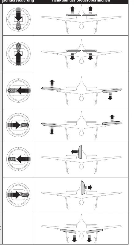
- Control surface diagrams illustrate the correct movement of the rudder, elevator, and ailerons in response to transmitter inputs.
- Wiring diagram for the AR637T receiver details the channel assignments for gas, ailerons, elevator, rudder, landing gear, and flaps.
Model compatibility
- Requires a 6-channel transmitter with DSM2/DSMX technology.
- Recommended battery: 5000mAh 6S 22.2V Smart LiPo (SPMX50006S30).

Manual page author
Michael Turner
Technical manual editor
Reviews PDF manuals for structure, safety notes, and practical product details so readers can find the right information quickly.