Computers / Laptops
Maintenance and Service Guide for HP 14s Laptop PC
Comprehensive maintenance and service guide for the HP 14s Laptop PC. Includes detailed disassembly procedures, component replacement instructions, specifications, and diagnostic tools for authorized service providers.
Table of contents
Manual images
Click an image to enlargeQuick guide from the manual
This document is intended for authorized service providers. Before performing any maintenance, ensure the computer is completely shut down and disconnected from all power sources and external devices. Always use a grounded workstation and anti-static equipment to prevent electrostatic discharge (ESD) damage to sensitive components. Required tools include a non-conductive pry tool and a magnetic Phillips P1 screwdriver.
Product description
The HP 14s Laptop PC features 10th generation Intel Core processors, a 14-inch FHD display, and supports various storage configurations including 2.5-inch SATA hard drives and M.2 SSDs. Memory is provided via a single SODIMM slot, though it is not customer-accessible or upgradeable.
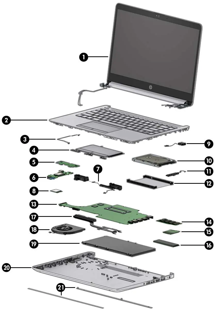
Illustrated parts catalog
The manual provides detailed exploded views of the computer to assist in identifying components. Key assemblies include the display assembly, keyboard/top cover, system board, battery, and various modules like WLAN and WWAN. Always refer to the specific spare part numbers listed in the manual when ordering replacements.
Removal and replacement procedures
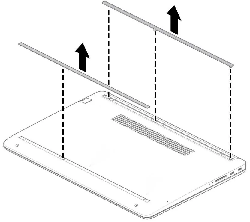
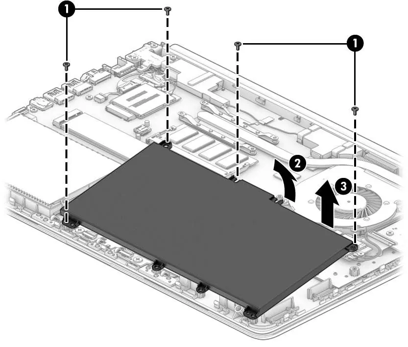
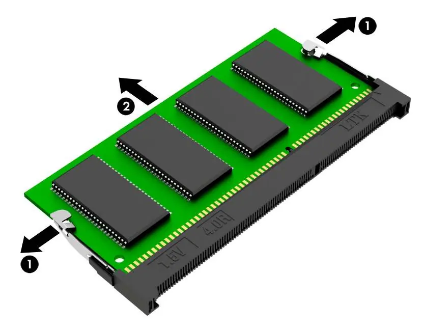
This section outlines the step-by-step process for disassembling the laptop. Key procedures include:
- Preparation: Always shut down the computer and disconnect power and external devices before starting.
- Bottom cover: Remove rubber feet and screws to access internal components.
- Battery: Disconnect and remove the 3-cell, 41 Whr battery after removing the bottom cover.
- Memory module: Spread retention clips to release the module.
- Solid-state drive: Remove the M.2 screw to pull the drive from the socket.
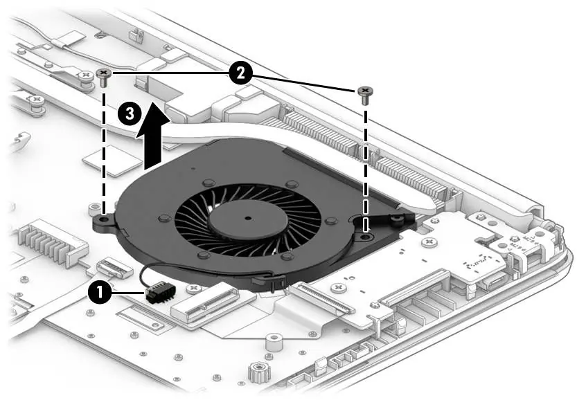
- Fan and Heat sink: Disconnect cables and remove screws in the indicated order to access the thermal module.
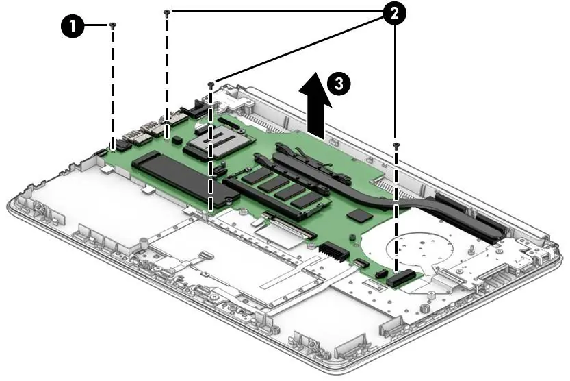
- System board: Disconnect all cables (display, antennas, power, USB, keyboard) before removing the board.
- Display assembly: Requires careful handling of hinges and antenna cables.
BIOS and Diagnostics
The computer includes a Setup Utility (BIOS) for hardware configuration and HP PC Hardware Diagnostics for troubleshooting. You can access these tools by pressing specific keys (f10 for BIOS, esc/f2 for diagnostics) during startup. If the computer fails to boot, use the diagnostic tools to generate a Failure ID code for support.
Specifications
The device operates within specific environmental limits: 5°C to 35°C for operation. It supports 18.5 V dc input power. Detailed specifications for the display, M.2 SSD, and hard drives are provided to ensure compatibility during upgrades or repairs.
Safety and Recycling
Always follow local regulations for battery disposal. Do not dispose of batteries in general household waste. Ensure the AC adapter is not obstructed and does not contact skin or soft surfaces during operation to prevent overheating.
Manufacturer information
HP Inc.
Practical help
Common problems
Computer not starting
Check battery charge, perform a hard reset, or use HP PC Hardware Diagnostics UEFI to identify hardware failures.
Overheating
Ensure air vents are not obstructed; do not place the device on soft surfaces like pillows or rugs during operation.
Battery not charging
Verify the AC adapter connection. Check the battery light: Amber indicates charging, White indicates fully charged.
Before use
- Ensure you have a non-conductive pry tool and a magnetic Phillips P1 screwdriver.
- Shut down the computer completely (do not use Sleep or Hibernation).
- Disconnect the power cord and all external devices.
- Use an anti-static wrist strap or grounded workstation to prevent ESD damage.
- Keep subassemblies and screws organized away from the work area.
Images and diagrams
- Exploded views show the order of component removal.
- Numbered callouts correspond to specific screws or parts in the removal procedures.
Model compatibility
- Display assemblies are offered as subcomponents only.
- Wireless modules must be authorized for your specific region to prevent system errors.

Manual page author
Emily Carter
User documentation editor
Prepares concise manual descriptions and highlights the most useful setup, operation, and maintenance information for readers.