Computers / Laptops
HP ENVY 17m/17 Laptop PC Maintenance and Service Guide
A comprehensive maintenance and service guide for the HP ENVY 17m/17 Laptop PC. This document provides detailed instructions for component identification, disassembly, replacement procedures, BIOS setup, diagnostics, and technical...
Quick answers from the manual
Quick answer
- This guide provides instructions for authorized service providers to perform maintenance, disassembly, and component replacement on the HP ENVY 17m/17 Laptop PC. p. 1, 25
Key actions
- Accessing Setup Utility (BIOS) p. 59
- Starting HP PC Hardware Diagnostics (UEFI) p. 61
Problems and fixes
Computer not responding
Press and hold the power button for at least 5 seconds to turn off the computer.
p. 19Technical specifications
| Parameter | Value | Meaning | Pages |
|---|---|---|---|
| Operating Voltage | 19.5V / 19V | Input power requirements | p. 76 |
Where to find it in the PDF
- Product Description p. 9
- Removal and Replacement Procedures p. 25
- Specifications p. 76
Table of contents
Manual images
Click an image to enlargeImportant Information from the Manual
This document is intended for HP authorized service providers only. It contains detailed procedures for the maintenance, disassembly, and replacement of components for the HP ENVY 17m and 17 Laptop PCs. Always follow electrostatic discharge (ESD) precautions when handling internal components.
Tools Required
- Flat-bladed screwdriver
- Magnetic screwdriver
- Phillips P0 and P1 screwdrivers
Component Identification
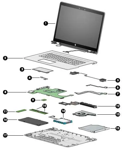
The manual provides detailed diagrams for identifying external components, including:
- Right side: Optical drive, USB 3.x ports, power connector.
- Left side: Security cable slot, RJ-45, HDMI, USB ports, audio jack, memory card reader.
- Display: WLAN antennas, camera, microphones.
- Keyboard area: TouchPad, power button, speakers, special keys.
Removal and Replacement Procedures
Before performing any service, shut down the computer, disconnect all external devices, and unplug the AC adapter. Key procedures include:
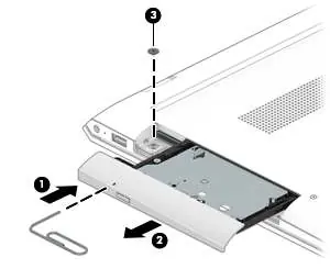
- Base Enclosure: Remove the optical drive, rubber strip, and screws to access internal components.
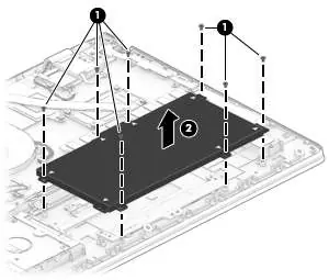
- Battery: Remove the base enclosure, then remove the 7 screws securing the battery.
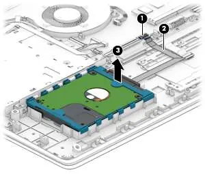
- Hard Drive: Disconnect the cable and lift the drive from the chassis.
- Solid-State Drive (SSD): Remove the Phillips screw and pull the drive away from the slot at an angle.
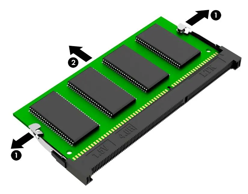
- Memory: Spread the retaining tabs on each side of the module to release it.
- WLAN Module: Disconnect antenna cables and remove the securing screw.
- Fan and Heat Sink: Disconnect cables and remove securing screws to access the thermal assembly.
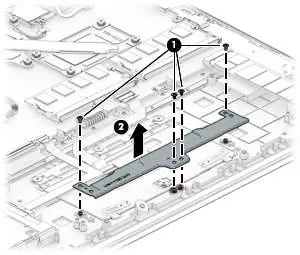
- System Board: Disconnect all ribbon cables and remove the securing screws.
BIOS and Diagnostics
The manual covers using the Setup Utility (BIOS) to manage system settings and HP PC Hardware Diagnostics (UEFI) to test hardware functionality. Access these utilities by pressing esc during startup, then selecting the appropriate function key (f10 for BIOS, f2 for diagnostics).
Recovery
Options for system recovery include using HP Recovery Manager, HP Recovery media, or the HP Recovery partition. Always back up personal data before beginning recovery procedures.
Specifications
The guide includes detailed technical specifications for the computer, display, hard drive, and M.2 solid-state drives, including dimensions, power requirements, and operating temperature ranges.
Manufacturer information
HP Inc.
Practical help
Common problems
Computer not responding
Press and hold the power button for at least 5 seconds to force a shutdown.
Hard drive not detected
Verify the hard drive cable connection to the system board.
System overheating
Ensure air vents are not obstructed and the internal fan is functioning correctly.
Before use
- Shut down the computer completely.
- Disconnect all external devices.
- Unplug the AC adapter.
- Use a static-safe workstation.
- Use a magnetic screwdriver for small screws.
Specs in practice
- Operating Voltage
- 19.5V DC @ 3.33A (65W) or 19V DC @ 4.62A (90W)
- Operating Temperature
- 5°C to 35°C (41°F to 95°F)
- Relative Humidity
- 10% to 90% (noncondensing)
Images and diagrams
- Exploded view of major components for identification.
- Component location diagrams for ports and buttons.
- Step-by-step disassembly diagrams for internal parts.
Model compatibility
- Supports DDR4-2400 memory (downgrades to 2133).
- Supports M.2 SSD (SATA/PCIe).
- Supports 2.5-inch SATA hard drives.

Manual page author
Michael Turner
Technical manual editor
Reviews PDF manuals for structure, safety notes, and practical product details so readers can find the right information quickly.