Computers / Laptops
Maintenance and Service Guide for HP OmniBook 5 Flip 14 inch 2-in-1 Laptop PC
Comprehensive maintenance and service guide for the HP OmniBook 5 Flip 14 inch 2-in-1 Laptop PC. Includes detailed component removal and replacement procedures, spare parts catalog, BIOS setup, system diagnostics, and technical...
Quick answers from the manual
Quick answer
- This guide provides maintenance and service procedures for the HP OmniBook 5 Flip 14 inch 2-in-1 Laptop PC, including component removal, replacement, and system diagnostics. p. 1, 30, 41
Key actions
- Prepare for disassembly p. 30
- Remove the bottom cover p. 30, 38
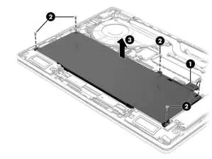
- Remove the battery p. 33, 41
Problems and fixes
Swollen battery
Discontinue using the notebook and contact HP for replacement.
p. 86Maintenance and reset
- Reset this PC p. 69
Technical specifications
| Parameter | Value | Meaning | Pages |
|---|---|---|---|
| Weight | 1650 g (3.64 lbs) | Total weight of the computer. | p. 87 |
Where to find it in the PDF
- Product description p. 8
- Illustrated parts catalog p. 15
- Removal and replacement procedures p. 30, 41
Table of contents
Manual images
Click an image to enlargeQuick guide from the manual
This document is a comprehensive maintenance and service guide for the HP OmniBook 5 Flip 14 inch 2-in-1 Laptop PC. It is intended for use by authorized service providers and users performing Customer Self-Repair (CSR). Before performing any maintenance, ensure the computer is shut down, disconnected from power, and all external devices are removed. Always follow electrostatic discharge (ESD) precautions to prevent damage to internal components.
Product description
The HP OmniBook 5 Flip 14 inch 2-in-1 Laptop PC features various configurations, including Intel Core processors, multiple memory options (LPDDR5/5X), and PCIe NVMe solid-state drives. The device includes a 14-inch display, dual speakers, and various ports including USB Type-C with Power Delivery and DisplayPort support.
Removal and replacement procedures
The guide categorizes parts into Customer Self-Repair (CSR) and Authorized Service Provider parts. Important: Accessing parts designated for authorized service providers may void your warranty. Always note screw sizes and locations during disassembly.
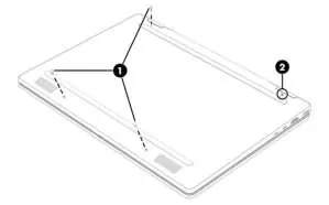
- Bottom cover: Requires removing three Phillips screws and loosening one captive screw.
- Battery: Requires a revive kit for new battery installation. Do not puncture or twist the battery.
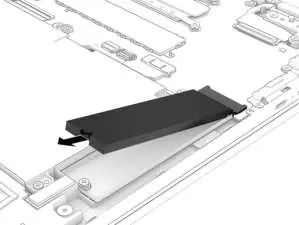
- Solid-state drive (SSD): Accessible after removing the bottom cover and battery.
- System board: Requires removal of the SSD, WLAN module, and heat sink before the board can be removed.
BIOS and diagnostics
The Setup Utility (BIOS) can be accessed by turning on the computer and pressing f10. The guide provides detailed steps for updating the BIOS and using HP PC Hardware Diagnostics (Windows and UEFI) to troubleshoot hardware failures, including generating failure ID codes for support.
Specifications
The laptop operates within specific temperature ranges (5°C to 35°C operating) and supports various USB-C power adapters (45W/65W). Detailed dimensions, weight, and SSD transfer rates are provided in the technical specifications section.
Battery safety
If you notice battery swelling, stop using the notebook immediately. Swollen batteries are not a safety issue but result from gas generation due to normal degradation. Contact HP support for replacement options.
Manufacturer information
HP Inc.
Practical help
Common problems
Battery swelling
Stop using the notebook immediately and contact HP support for replacement options.
System not booting
Use HP PC Hardware Diagnostics (UEFI) to isolate hardware failures or check BIOS settings.
Static damage during repair
Always use a grounded work surface, wrist straps, and static-safe containers for components.
Before use
- Shut down the computer completely.
- Disconnect the power cord from the computer.
- Disconnect all external devices.
- Prepare a clean, static-free workspace.
- Use a magnetic Phillips P1 screwdriver.
- Use a nonconductive, nonmarking pry tool.
Specs in practice
- Operating Temperature
- 5°C to 35°C (41°F to 95°F) for safe operation.
Images and diagrams
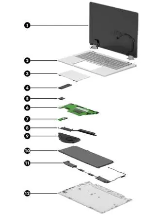
- Exploded view of major components for identification.
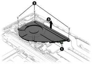
- Step-by-step illustrations for bottom cover and battery removal.
- Detailed routing paths for cables around the fan and hinges.
Model compatibility
- Spare parts may vary by model (14-fp0xxx, 14-km0xxx, 14-km1xxx).
- Some features like 'select products only' may not be available on all units.

Manual page author
Michael Turner
Technical manual editor
Reviews PDF manuals for structure, safety notes, and practical product details so readers can find the right information quickly.