Computers / Laptops
User Guide for HP Ethernet 1Gb 4-port 331T Adapter
Comprehensive user guide for the HP Ethernet 1Gb 4-port 331T Adapter. Includes installation instructions, LED indicator status, cable requirements, and technical specifications.
Quick answers from the manual
Quick answer
- The HP Ethernet 1Gb 4-port 331T Adapter is a 4-port 10/100/1000BASE-T network adapter. Installation requires powering down the server, inserting the card into a PCI Express slot, and connecting UTP CAT5 cables. p. 6, 8, 9
Key actions
- Install adapter in PCI Express slot p. 9
First start
- Power down server, install adapter, reconnect power. p. 9
Problems and fixes
No link established
Check cable connection and power status.
p. 6, 7Technical specifications
| Parameter | Value | Meaning | Pages |
|---|---|---|---|
| Data rate | 1 Gb/s per port | 4 Gb/s combined, full-duplex | p. 11 |
Where to find it in the PDF
- Installation p. 8, 9, 10
- Specifications p. 11, 12
Table of contents
Manual images
Click an image to enlargeQuick guide from the manual
This guide provides essential information for installing and operating the HP Ethernet 1Gb 4-port 331T Adapter. Always power down the server and disconnect the power cord before performing any hardware installation to prevent electric shock or equipment damage.
Overview
The HP Ethernet 1Gb 4-port 331T Adapter is a four-port, 10/100/1000BASE-T Ethernet adapter. It features Energy Efficient Ethernet, IEEE 1588/Precision Time Protocol support, and PCI Express v2.0 compatibility.
Installing an adapter in a server
Before installation, ensure you are protected against electrostatic discharge (ESD). Use a wrist strap or other grounding methods.
- Power down the server.
- Remove the power cord and the server access panel.
- Identify the PCI Express option slot.
- Remove the cover bracket from the PCI Express slot.
- Firmly seat the adapter in the PCI Express slot and secure the adapter bracket.
- Replace the access panel and reconnect the power cord.
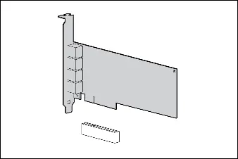
Installing a low profile bracket
If you are using a 1U server, you may need to install the low profile bracket.
- Use a slotted screwdriver to remove the two board lock screws at the top and bottom of the connector.
- Remove the standard profile bracket.
- Place the low profile bracket over the connector, ensuring not to damage the connector.
LED indicators
The adapter features LED indicators for Link (L) and Activity (A) for each port.
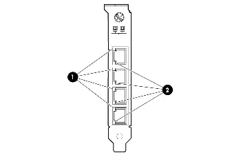
- Link Off: No link established or no power.
- Link On (Yellow): Link established at 10 Mb/s or 100 Mb/s.
- Link On (Green): Link established at 1 Gb/s.
- Activity Off: No network activity.
- Activity Flashing (Green): Network activity detected.
Specifications
The adapter uses UTP CAT5 or better cabling. CAT5e is recommended for new installations. The maximum distance for Gigabit over copper is 100 meters (328 feet).
Manufacturer information
HP Inc.
Practical help
Common problems
No link established
Check cable connection and ensure the adapter is receiving power.
Adapter not recognized
Ensure the adapter is firmly seated in the PCI Express slot.
Before use
- Power down the server
- Unplug the power cord
- Use ESD protection (wrist strap)
- Verify PCI Express slot availability
Specs in practice
- Max distance
- 100 meters (328 feet)
Images and diagrams
- LED indicators show link speed and activity status.
- Low profile bracket installation requires removing two board lock screws.
Model compatibility
- Requires PCI Express v2.0 slot.
- Compatible with UTP CAT5 or better cabling.

Manual page author
Michael Turner
Technical manual editor
Reviews PDF manuals for structure, safety notes, and practical product details so readers can find the right information quickly.