Tools / Woodworking Tools
User Manual for Charnwood 1420V Electronic Variable Speed Lathe
Quick guide for the Charnwood 1420V Electronic Variable Speed Lathe. Includes assembly, speed adjustment, maintenance, and troubleshooting steps.
Table of contents
Manual images
Click an image to enlargeQuick guide from the manual
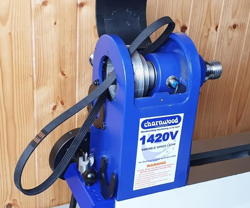
The Charnwood 1420V is a hobby-grade wood lathe designed for weekend DIY and woodworking enthusiasts. It features electronic variable speed control and an indexing system. Before operation, ensure the machine is properly earthed, guards are in place, and you are wearing appropriate safety gear, including eye and ear protection. The machine is rated for a maximum of 100 hours of use annually.
Safety Rules
- Always read the manual thoroughly before operation.
- Keep guards in place and in working order.
- Remove adjusting keys and spanners before switching the machine on.
- Do not force the machine; use it at the rate for which it is designed.
- Disconnect the machine from the power source before servicing or changing the drive belt.
- Never leave the machine running unattended.
- Always wear a face or dust mask if the operation creates dust.
- Never attempt to adjust the workpiece while the lathe is in motion.
Assembly
The lathe is packed in one carton and requires two people to lift. Unpack and check that all loose items are present, including the tool rest, banjo, centers, and service tools. Decide on a mounting location where the spindle height is approximately level with your elbow. While the lathe is stable enough to be used without fixing, it is recommended to bolt it to a suitable stand or bench for larger diameter blanks (6 inches plus) or unbalanced pieces. If bench mounting, install the four rubber feet into the threaded holes on the underside.
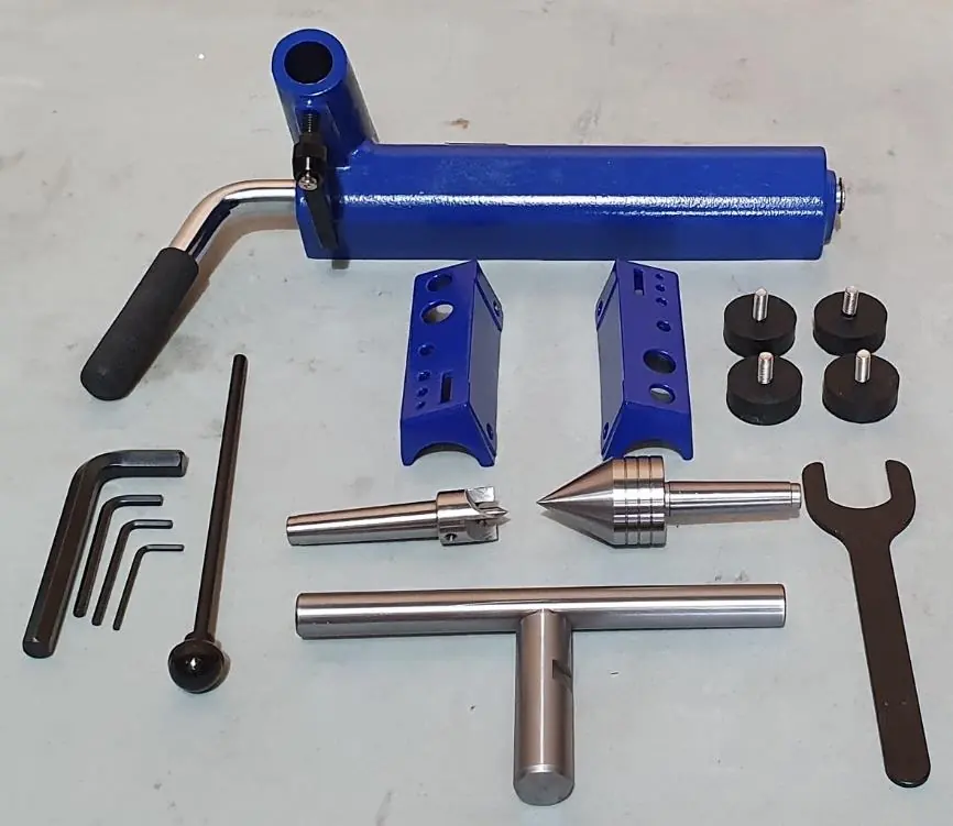
Tool Rest Assembly: Slide the tailstock off the bed. Line up the tool rest banjo and rotate the cam lock lever so the clamping plate is in its lowest position. Slide the banjo onto the bed, fit the tool rest, and lock it with the height lock ratchet handle. Refit the tailstock.
Adjusting Spindle Speed
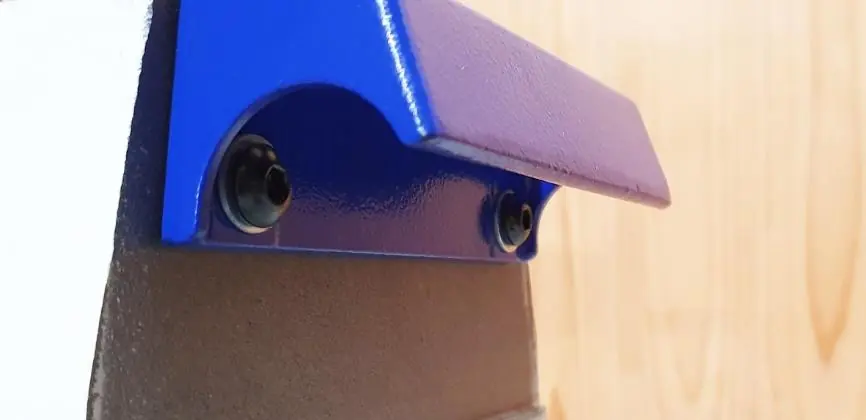
The lathe offers three speed ranges obtained by changing the drive belt position. To adjust: remove the bottom pulley access door by loosening the four bolts with a 3mm hex key. Open the upper belt cover. Loosen the belt tension locking handle, lift the tension lever, and move the belt to the desired pulley set. Release the locking lever to tension the belt and re-tighten. Speed ranges are: 250-750rpm (Left), 600-1700rpm (Centre), and 1200-3550rpm (Right).
Using the Lathe
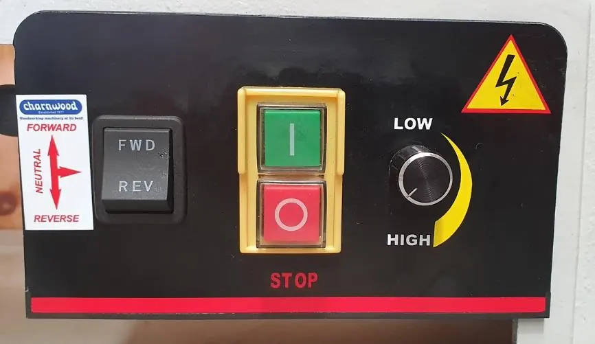
The tailstock can be adjusted by rotating the cam lock lever to slide it along the bed. Fine adjustment of the tail center is made by undoing the tail center lock and using the handwheel. The tool rest height and position are adjustable via the height lock and cam lock lever. Always stop the lathe completely before switching between forward and reverse directions.
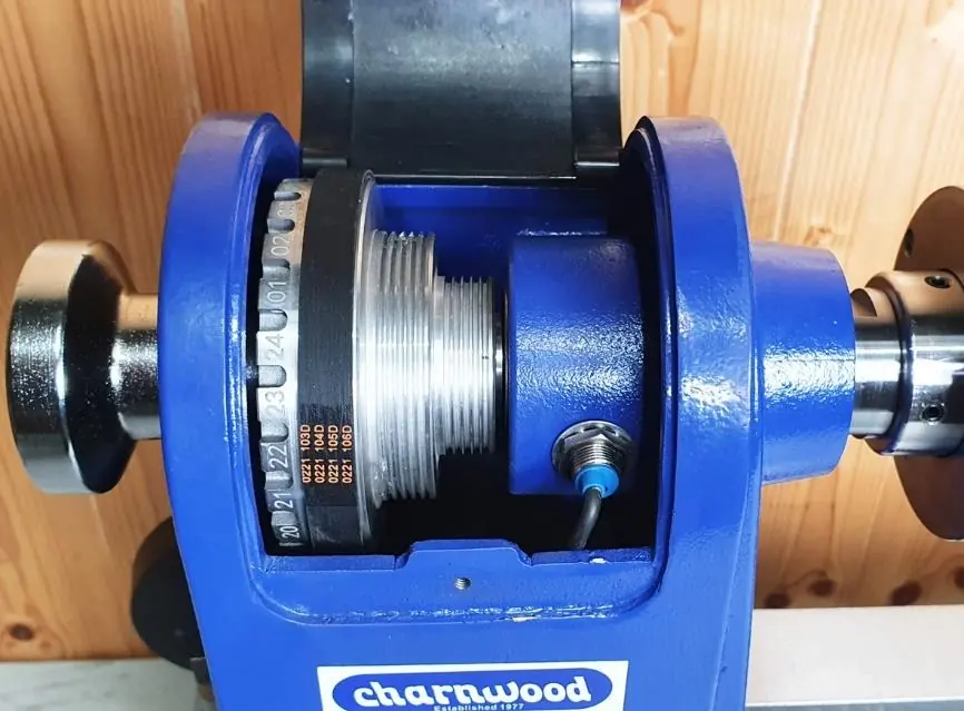
Indexing System
The indexing system allows the spindle to be locked in 24 positions (every 15 degrees). Open the top belt pulley cover to expose the indexing ring. Line up the desired position with a mark on the headstock casting, then pull out and rotate the indexing pin until it springs forward to lock the spindle. Never use the indexing pin as a spindle lock when removing accessories.
Routine Maintenance
Drive Belt: If the belt becomes worn, remove the bottom pulley access door, remove the handwheel, and swing the cover plate away to access the belt. Replace the belt and ensure V-grooves are correctly seated.
Motor Brushes: Inspect carbon brushes after approximately 500 hours of use or when worn down to 7mm. Remove the motor from the machine, unscrew the brush covers on either side, and replace both brushes simultaneously.
Troubleshooting
If the machine will not start, check the power supply, fuses, and ensure the indexing pin is disengaged. If the spindle stalls but the motor runs, increase the drive belt tension. If the motor overheats, reduce the load by making shallower cuts and ensure the area around the motor is clear of shavings.
Practical help
Common problems
Machine will not start
Check plug connections, replace blown fuses, or ensure the indexing pin is disengaged.
Spindle stalls but motor runs
The drive belt is loose; increase belt tension.
Motor overheating
Reduce load by making shallower cuts and clear shavings from around the motor.
Spindle rotation slows during cut
Reduce depth of cut, sharpen chisels, replace worn carbon brushes, or increase belt tension.
Before use
- Ensure all guards are in place and functional.
- Remove all chuck keys and spanners.
- Verify the workpiece is secure and balanced.
- Check rotation speed setting before starting.
- Wear eye and ear protection.
- Ensure the work area is clean and well-lit.
Specs in practice
- Spindle Thread
- M33 x 3.5mm.
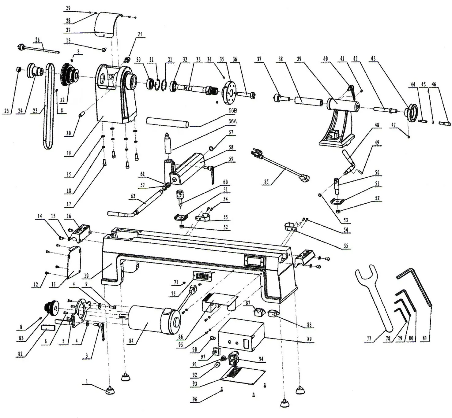
Images and diagrams
- Parts drawing illustrates the assembly of the headstock, tailstock, and motor components.
- Wiring diagram shows the connections for the speed control board, potentiometer, and switches.
Model compatibility
- Hobby rating: 100 hours maximum annual use.
- Not suitable for industrial or continuous production use.

Manual page author
Michael Turner
Technical manual editor
Reviews PDF manuals for structure, safety notes, and practical product details so readers can find the right information quickly.