Lighting / Controllers & Dimmers
User Manual for Iskydance DL 4-Channel DMX512 Decoder
Comprehensive user guide for the Iskydance DL 4-Channel DMX512 Decoder. Includes installation instructions, wiring diagrams, DMX mode configuration, stand-alone RGB/dimmer settings, and troubleshooting steps.
Table of contents
Manual images
Click an image to enlargeQuick Guide
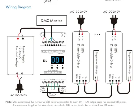
The Iskydance DL is a 4-channel DMX512 decoder designed for 0/1-10V dimming control. It supports RDM functions, stand-alone RGB/RGBW modes, and standard DMX mode. Key installation requirements include a 12-24VDC power supply and proper wiring to dimmable drivers. Ensure the number of LED drivers per output does not exceed 50 pieces, and wire length does not exceed 50 meters.
Product Overview
The device features a digital numeric display for setting DMX addresses and system parameters. It supports 1, 2, or 4-channel output modes and allows for linear or logarithmic dimming curves. The unit is DIN rail mountable.
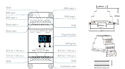
Installation and Wiring
Wiring Procedure:
- Connect the 12-24VDC power supply to the POWER IN terminals.
- Connect the DMX signal wires to the DMX IN terminals.
- Connect the 0/1-10V signal output wires to the corresponding dimmable drivers.
- Ensure correct polarity for all connections.
Mounting: The device is designed for DIN rail mounting (TS-35/7.5 or TS-35/15).
System Parameter Settings
To enter system parameter settings, long press the M and Left Arrow keys for 2 seconds. Use the M key to switch between items and the arrow keys to adjust values:
- Decode Mode: Select 1-channel (d-1), 2-channel (d-2), or 4-channel (d-4) decode.
- 0/1-10V Output: Switch between 0-10V (0-0) or 1-10V (1-0).
- Dimming Curve: Switch between linear (C-L) or logarithmic (C-E).
- Default Output Level: Set default brightness (d00 to dFF) when no DMX signal is present.
- Automatic Blank Screen: Enable (bon) or disable (boF) the display timeout.
Operation Modes
DMX Mode: Automatically enters when a DMX signal is detected. Use arrow keys to set the DMX start address (001-512).
Stand-alone RGB/RGBW Mode: Short press M until P01-P24 is displayed. Use arrow keys to change the dynamic mode. Long press M to adjust speed, brightness, and W-channel brightness.
Stand-alone Dimmer Mode: Short press M until L-1-L-8 is displayed. Each mode allows independent brightness adjustment for each channel.
Troubleshooting
If you encounter issues, check the following:
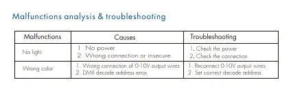
- No Light: Verify power supply and check for secure connections.
- Wrong Color: Check for incorrect 0-10V output wiring or DMX address errors.
Practical help
Common problems
No light output
Check the power supply connection and ensure all wires are secure.
Wrong color output
Verify the 0-10V output wiring and ensure the DMX decode address is set correctly.
Before use
- Ensure power supply is 12-24VDC.
- Verify DMX master console is compatible with DMX512 protocol.
- Check that LED drivers are compatible with 0/1-10V signals.
- Ensure wiring polarity (D+, D-, GND) is correct.
- Confirm DIN rail type (TS-35/7.5 or TS-35/15).
Specs in practice
- Input Voltage
- 12-24VDC required for operation.
- Output Signal
- 0/1-10V analog signal for dimmable drivers.
- Operating Temperature
- -30°C to +55°C.
Images and diagrams
- The wiring diagram illustrates the connection from the DMX Master to the Decoder, and subsequently to the Dimmable Drivers and LED strips.
- Mechanical diagrams show the dimensions (45mm, 35.5mm, 67mm, 48mm) for DIN rail installation.
Model compatibility
- Maximum 50 LED drivers per 0/1-10V output.
- Maximum wire length from decoder to LED driver is 50 meters.

Manual page author
Emily Carter
User documentation editor
Prepares concise manual descriptions and highlights the most useful setup, operation, and maintenance information for readers.