Lighting / Controllers & Dimmers
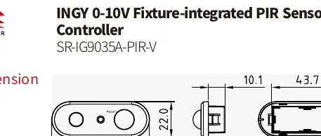
User Manual for Sunricher INGY 0-10V Fixture-integrated PIR Sensor Controller SR-IG9035A-PIR-V
Quick guide for the Sunricher INGY 0-10V PIR Sensor Controller (SR-IG9035A-PIR-V). Includes wiring instructions, installation precautions, reset procedures, and technical specifications.
Table of contents
Manual images
Click an image to enlargeQuick Guide from the Manual
The Sunricher INGY 0-10V Fixture-integrated PIR Sensor Controller (SR-IG9035A-PIR-V) is designed for lighting control within a Wirepas mesh network. Important: Do not install the device while power is applied. Avoid exposing the device to moisture. The device supports magnetic reset and standard button reset for network management.
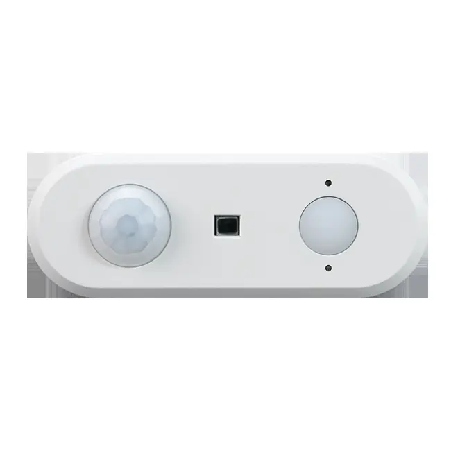
Product Overview
The controller features a PIR lens for motion detection, a light sensor for ambient light detection and daylight harvesting, and a reset key. It supports kinetic energy switches and EnOcean switches (EWSSB and EWSDB).
Installation Precautions
To ensure optimal performance and avoid false alarms, follow these installation guidelines:
- Avoid areas with frequent temperature changes (e.g., near air conditioners, fans, refrigerators, ovens).
- Avoid areas with significant airflow.
- Do not face glass doors or windows directly to prevent interference from strong light or complex outdoor environments.
- Avoid installing opposite large, constantly moving objects (e.g., large trees or bushes outdoors).
- Keep the detection range free from obstacles like screens, furniture, or large potted plants.
- Avoid areas exposed to direct sunlight.
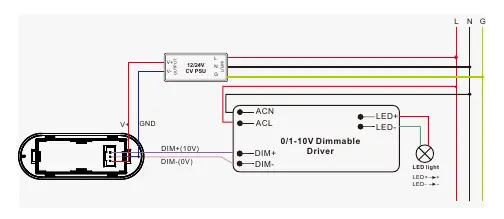
Wiring
Perform wiring according to the connection diagram. Ensure the 12-24VDC power supply is connected to the V+ and GND terminals. The 0-10V dimmable driver connects to the DIM+ and DIM- terminals. Ensure all connections are secure before applying power.
Operation and Reset
To reset the controller:
- Button Reset: Press and hold the Reset button on the controller for over 5 seconds until the indicator flashes.
- Magnetic Reset: Touch the top part of the sensor with a magnet for 5 seconds.
Successful reset is indicated by the LED flashing quickly.
Technical Specifications
- Input: 12-24VDC
- Output: 0/1-10V, Max 20mA
- Dimming Method: PWM (Logarithmic curve)
- Operating Temperature: 0°C to 45°C
- Relative Humidity: 8% to 80%
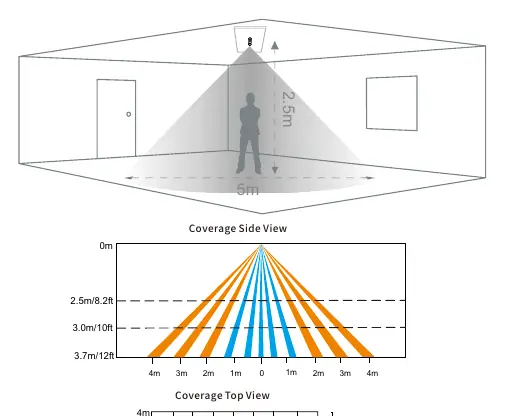
- Mounting Height: 2.5m
- Detection Area: 5m diameter at 2.5m height
Detection Pattern
The detection area is divided into two movement types: slow movement (person moving less than 0.3m/s) and quick movement (person moving greater than 0.4m/s). The sensor provides a 360-degree coverage pattern suitable for indoor environments.
Practical help
Common problems
False alarms or erratic triggering
Ensure the sensor is not facing glass doors/windows, is away from heat sources (AC, ovens), and is not obstructed by large plants or furniture.
Device not responding or needs network removal
Perform a reset by holding the Reset button for 5 seconds or using a magnet on the top of the sensor for 5 seconds until the LED flashes.
Before use
- Ensure power is disconnected before starting installation.
- Verify the power supply is 12-24VDC.
- Confirm the mounting location is free from significant airflow and heat sources.
- Check that the mounting height is approximately 2.5m for optimal coverage.
- Ensure the 0-10V driver is compatible with the wiring diagram.
Images and diagrams
- The wiring diagram illustrates the connection between the 12/24V CV PSU, the controller, and the 0-10V Dimmable Driver.
- The detection pattern diagrams show the side and top views of the sensor's coverage area, distinguishing between slow and quick movement detection.
Model compatibility
- Compatible with Wirepas mesh network.
- Supports kinetic energy switches.
- Supports EnOcean switches (EWSSB and EWSDB).

Manual page author
David Miller
Documentation analyst
Organizes user manual content into clear summaries, with attention to model details, product context, and everyday usability.