Power / Solar Systems
User Guide for iTechworld Pure Sine Wave Inverter
A comprehensive user guide for the iTechworld Pure Sine Wave Inverter (2000W and 3000W models). This manual covers installation, wiring diagrams, battery connection, safety precautions, and technical specifications.
Quick answers from the manual
Quick answer
- The iTechworld Pure Sine Wave Inverter converts 12V DC battery power to 240V AC power. Installation requires connecting the inverter to a 12V battery system using appropriately sized cables and fuses, ensuring proper chassis grounding, and mounting the unit in a well-ventilated, dry location. p. 3, 7, 8
Key actions
- Connect the inverter to the battery using the positive and negative terminals, ensuring a fuse is installed on the positive cable. p. 8, 12
- Mount the inverter horizontally on a flat surface with 100mm of ventilation space. p. 11
First start
- Ensure the battery is charged, plug the appliance into the 240V output, turn on the inverter, then turn on the appliance. p. 14
Problems and fixes
Fault LED flashes once
Over/Under Voltage Protection. Isolate for 60 seconds, ensure input voltage is 10.5V - 15.5V.
p. 6
Fault LED flashes 4 times
AC Output Overload. Ensure total draw does not exceed rated maximum.
p. 6Technical specifications
| Parameter | Value | Meaning | Pages |
|---|---|---|---|
| Input Voltage Range | 10.5V - 15.5V | Operating DC voltage range | p. 16 |
| Output Waveform | Pure Sine Wave | Type of AC output | p. 16 |
Where to find it in the PDF
- Overview p. 3
- Installation p. 7, 8, 9, 10
- Operation p. 14, 15
- Specifications p. 16
Table of contents
Manual images
Click an image to enlargeQuick guide from the manual
The iTechworld Pure Sine Wave Inverter is designed to convert 12V battery power into reliable 240V AC power. Important: Professional installation by a licensed electrician is recommended. Ensure the inverter is mounted in a dry, well-ventilated area with at least 100mm of clearance. Always verify that your battery chemistry (SLD, AGM, GEL, or LiFePO4) is compatible and that the total wattage of connected appliances does not exceed the inverter's rated capacity.
Product overview
The inverter features an input side with positive/negative terminals and a cooling fan, and an output side with 240V sockets, a power switch, LED indicators, and a remote port. The chassis includes mounting brackets and a grounding point.

Installation
AC output installation
Ensure the unit is switched off and no devices are plugged in before installation. We strongly recommend this installation be performed by a licensed electrician.
Chassis grounding
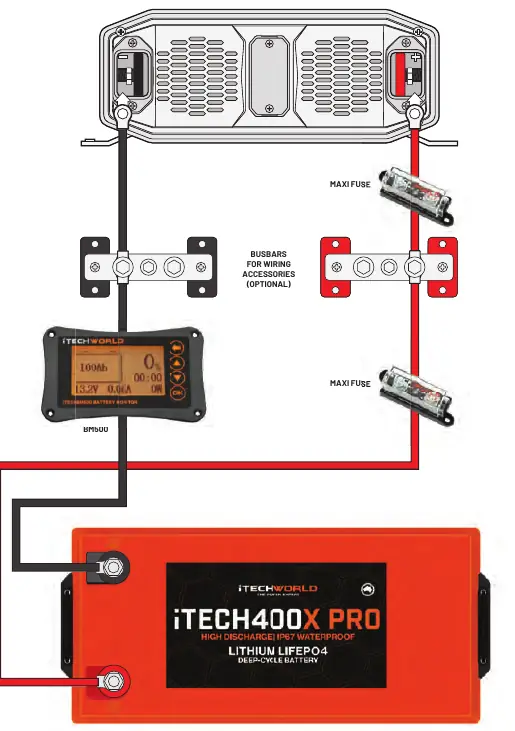
Grounding is mandatory. Attach a copper cable (at least 4mm²) from the grounding point on the mounting bracket to a suitable earthing point, such as the vehicle frame or the battery's grounded negative terminal.
Connecting the battery
- Ensure you have the correct cable sizes and fuses.
- Remove plastic terminal covers and nuts/washers from the inverter terminals.
- Attach positive and negative cables to their respective terminals. Secure with nuts.
- Reinstall terminal covers.
- Connect cables to the battery, attaching the positive terminal first, followed by the negative.
- Ensure an appropriately sized fuse is installed on the positive cable close to the battery.
Remote installation
The optional remote allows operation from a distance. Drill 2mm holes at mounting points and cut a hole in the surface according to the dimensions (86mm x 86mm). Secure the remote with M3 screws and connect the RJ12 cable.
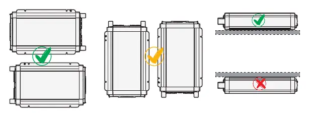
Mounting requirements
- Ventilation: Provide at least 100mm space around the unit.
- Orientation: Mount horizontally on a flat surface. Do not mount upside down.
- Environment: Keep dry, cool (0°C to 40°C), and free from dust and fumes.
Operation
- Ensure the battery has sufficient charge.
- Plug the appliance into the AC 240V output.
- Turn on the inverter using the power switch.
- Turn on your appliance(s).
Troubleshooting
The inverter uses LED indicators to signal status. If a fault occurs, the Fault LED will flash:
- Flashes Once: Over/Under Voltage Protection. Ensure input voltage is 10.5V - 15.5V.
- Flashes Twice: AC Output Short Circuit. Inspect appliance and reconnect.
- Flashes 3 Times: Over/Under Temperature. Ensure temperature is between -10°C and 50°C.
- Flashes 4 Times: AC Output Overload. Ensure total draw does not exceed rated maximum.
- Flashes 5 Times: Internal Fault. Contact iTechworld service centre.
Manufacturer information
iTechworld
Practical help
Common problems
Inverter not turning on or fault light flashing
Check battery voltage (must be 10.5V-15.5V), check for short circuits, or ensure the load does not exceed the inverter's rated capacity.
Overheating
Ensure at least 100mm of ventilation space around the unit and that the operating temperature is between -10°C and 50°C.
Voltage drop
Position the inverter close to the battery (at least 300mm distance) and use thick enough cables as specified in the cable guide.
Before use
- Verify battery chemistry is SLD, AGM, GEL, or LiFePO4.
- Ensure cable size matches the length and model (e.g., 70mm² for 2000W 0-1m).
- Install a fuse on the positive cable close to the battery.
- Ensure 100mm ventilation space around the inverter.
- Mount the inverter horizontally on a sturdy surface.
- Ensure the inverter is switched off before connecting appliances.
Specs in practice
- Input Voltage Range
- The operating DC voltage range (10.5V - 15.5V) for the battery system.
- Output Waveform
- Pure Sine Wave, suitable for sensitive electronic appliances.
- Max Continuous Output
- The maximum power the inverter can supply continuously (2000W or 3000W depending on model).
Images and diagrams
- The Basic Setup Diagram shows the connection path from the battery through a fuse and optional busbars to the inverter.
- The Remote Installation diagram provides the cutout dimensions (86mm x 86mm) for mounting the remote control unit.
Model compatibility
- Compatible with 12V battery systems only.
- Supported battery chemistries: SLD, AGM, GEL, LiFePO4.
- Do not use with life support systems or medical equipment.

Manual page author
David Miller
Documentation analyst
Organizes user manual content into clear summaries, with attention to model details, product context, and everyday usability.